The tool I recommended you print instead would be able to mass produce the rubber tolling for casting the dies.
Thus the only cost is the amount of silicone you pour for each set of molds/
Platinum silicones are far more durable in casting urethanes- you should easily get 100 parts per mold.
I’ll take a look at your model and see what I can find out.
I imported the file and it had clearly corrupted geometry.
Most of the issues disappeared because of the software I imported it into…
But here are screen shots showing two overt errors.
In the upper picture you can see two little ‘shards’ that are floating in space separate from the model proper.
You won’t SEE these in your model- because they are the result of my software trying to make solids of the geometry in your file… what they imply is that there are spurious segments, or vertices unconnected to any other vertice that are bridging across the opening in your model.
The printer is seeing this as a “FILL” its trying to print.
The lower picture shows one of your numerals squashed and slanted over- this is the result of the top surface of the numeral being in the file, but not properly connected to the bottom of the numeral… your software tried to do a slice and stitch of the numeral but the sidewalls of the numeral did not export in the resulting file.
I corrected the numeral by copying and pasting one of the other numeral '1’s that imported correctly.
Here is a link to a version of the model that should print correctly.
However- in looking at the model I note that none of your numerals are correctly drafted for an injection tool. The edges of the numerals on the Lower sides ( facing the hole) are all Undercuts that will prevent the release of a rigid casting.
If you attempt to use the large triangular hole as an ejector pin, the result will be the fracturing of the edges of the numerals- or an inability to get the casting out of the cavity at all.
The printed resin tool is more likely to fracture than the urethanes you might fill it with, but you may well see damage to both tool and casting.
You might get away with casting Vinyl dies in this mold- but nothing rigid.
For something like this, the numerals should be modeled as very shallow rounded grooves such that no portion of an engraved numeral is less than 1 full degree of draft relative to the motion of the ejector pin.
wow thats a crazy flaw! my software doesent shoy any of that! at first i was surprised you found overhangs on the numerals, I think i must have mistakenly drafted in the wrong direction THAT part iseasily fixed. I really would like to know how the got that weird error in it. very strange.
I appreciate your thoughts on the tool design in general. I was thinking along similar lines regarding the numeral grooves. my original design had rounded grooves, but i removed all the fillets in an attempt to get a good print thinking it was the fillets causing the error. so think of this model as more of a test print at this point. I definatly have some draft direction mistakes to correct… The next question is how to prevent this in the future? I ran thie model through a two different “checkers” any suggestions on how to eliminate this? I apppreciate your fixed model, but I have alot of molds to work on and really dont expect you to fix them all.
Again I really appreciate the help.
I don’t think you realize how draft is going to affect your design.
Here is a screen shot showing in pink how much fill would be required to give your tool a 1% draft.
And generally speaking, 2% is considered the minimum allowable draft for rigid resin casting.
As you can see the draft from the 2 intersects the face with the 10 on it.
And even the vents on either side are undercut a little, too.
The lower shot shows what a split master I suggested would look like- the Two green hemispheres are registration features that I recommend you add to prevent the two tools from sliding side to side along the angles of the separation plane.
Here is a link to a model I exported of the Split master for this half.- once you print both halves of a split master- you can pour both sides of a silicone mold at once- and then put them together to make a complete mold.
But this allows you to make as many molds as you need to meet production or replace them as they wear- without having to print over and over. Its a set of tools for manufacturing molds.
This model does NOT have the green registration features I show in the screenshot. those features, if you add them, need to be added to mate from one side to the other,
The software I use is Freeform- which is the pre-eminent modeling app for modeling for print- but that most folks don’t feel they can afford. Freeform is a voxel modeler- which means it simply can not create a model that is not a qualified solid.
Just importing your model into Freeform solved most of its issues. I just had to fix the one messed up ‘1’ and delete the fugitive geometry and fill holes in the body of the model to make it printable.
To prevent this in the future is going to require a couple of things- first of which is a bit more experience on your part with actual draft and tooling limitations- just so you know what to look for. as well as more knowledge as to how computers represent solid objects and where faults can occur.
Adding fillets to your numbers was likely the primary issue- as LOTS of surface modelers corrupt geometry in doing operations like filleting.
However- I can tell you that filleting alone would not have solved the draft issues with this model.
You might consider a different app to model in- something like Modo or another subD modeler that has the measurement tools that zBrush lacks.
Also- I would point out the the numerals on the die are not well centered on their respective faces- which is more apparent in the second photo above as a positive shape.
IN re-reading your reply- I think I understand where your thinking is off.
You “drafted” each numeral about 2 degrees relative to the FACE of the die each numeral is on.
That is not how draft works on an injection mold.
Each injection tool has a direction of Draw- that is the direction the tool is pulled away to release the cast part.
In your tool, the direction of draw is defined by the ‘ejector pin’- the tapered hole you modeled in one face of the die.
Imagine that pin as a piston, pushing your part out of the mold… the part will try to move straight along the axis the pin moves… the edge of each numeral embossed into the cavity had to be drafted relative to this axis of motion.
As it is, the resin you inject into the cavity will fill under the lip of each numeral and harden there, each acting as an undercut preventing the part from moving in the direction the ejector is pushing.
In the picture I posted you can see the pink fill creating a sloping surface under these undercut edges that all taper toward the axis of draw at 1 degree. The steeper the face, the more noticeable the fill required to make the number drafted.
This allows the cast die to MOVE directly up and out of the tool in the direction the ejector is pushing… like a dixie cup being slid off the stack of other dixie cups.
I don’t want be too contrary to the awesome community support in this thread, but I do think the optics in your system are at least a little dirty. I would expect the numbered pillars in the Optics Test print to be much more square at the top. What did Formlabs Support say? My personal and unofficial guess is that there’s contamination on your galvanometer mirrors that will need to be cleaned to get your printer printing as sharp as it should be, unfortunately.
I went ahead and printed one of your files in High Temp V2 (wasn’t sure whether you were using V1 or V2, shouldn’t matter though), at 100µm layer thickness, and got this:
I didn’t have any problems with the geometry. From my one so-so photo, does the print look like the quality you want to be getting on this model?
I do agree with Sculptingman that if you’re casting rigid 2-part urethane (or other resin) parts, making a silicone mold is probably a good way to go, and might save you some headaches for this application vs. casting into a printed mold. Sometimes casting into a rigid printed mold can be a great idea, but in this case, since you appear to want relatively sharp 90-degree edges on every orientation of a 20-sided die, a rubber mold that isn’t as affected by draft angle is probably the way to go.
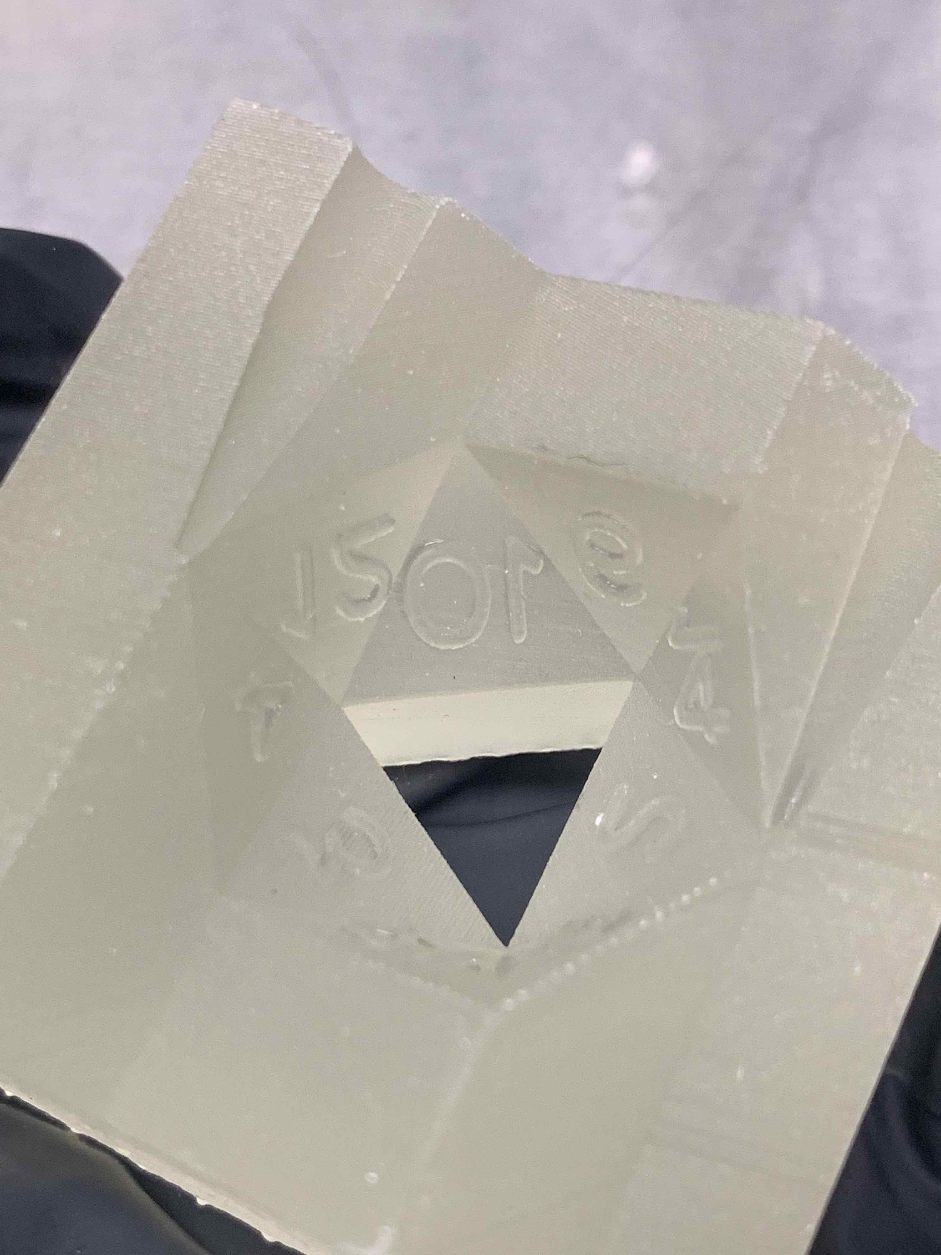
Curious-
did your test print come out with a deformed numeral 1 on the side marked ‘12’?
When I imported it it came in at less than half the height of the 2 next to it, and skewed to one side.
Also- which version of Preform and printer software were you running when you imported this?
I have noticed significant changes in Preform’s ability to correct corrupt geometry with successive versions.
I just checked. Using PreForm 2.19.2, and also MeshMixer, and in my print, the vertical of the 1 is perpendicular to the base of the 2, as it should be. But yeah, the 1 numeral is very short and extruded out at an angle instead o f perpendicular to the triangular face it’s on. (screenshot from MeshMixer but it looks the same in PreForm)
I’m on a 1.18 printer software at the moment but I do not think it is relevant. I do think that PreForm’s NetFabb integration (which does at least some of the lifting for geometry checking/repair) has changed over the past few versions, but I’d have to ask mgarrity to be sure.
All good points. I am a total novice to mold.design. im a controls.and electronics guy. But I work in new.product development so we are encouraged to experiment with stuff like this. One thing I did have draft modeled in the along the direction of pull “another” feature I removed in the hopes of removing variables. But yes I need to study up on draft strategy. I use solid works for all my design work, but it’s usually for mechanical/machine design. The mold tools options I hldot have a ton of experience with. I wonder where the corruption came from. The dice mold blank model I used was the Same as what I used in my older flexible molds. I wasn’t able to use drafted numerals on those molds because my numeral tff.files are custom made and those were vector graphic conversions full of all sorts of anamolies, which prevented.solidworks from cutting and drafts at all. This new.mold.used a 2d sketch of the original numerals and extruded cut this also explains the centering as well. At the time I wasn’t too concerned with numeral positioning yet. I wonder if that’s where the file.corruption occurred. I’ll look into the program you mentioned.
Thanks again for all the advise.
Yeah I know it’s a challenge to do this. getting the sharp edges is key feature. I also want a high gloss surface finish to my parts “which is why I wanted to use high temp resin so I can polish it” I was also hoping for more durabability I had pretty fast and easy success with the flexible resin molds.but they wear out pretty fast. And I had some issues with over clamping pressure. I am looking at the split master idea too.
1.19.2 is the current release and it’s what I’d recommend. When the next release comes out I’ll recommend that
You can find a bunch of old PreForm versions here PreForm older versions , and they should generally run just fine but I don’t think Formlabs makes them officially available for download, and I’m not aware of any current regression errors where some model is printed better with an older version of PreForm.
Yeah, I think you’ll be a lot happier if you can get your printer optics a bit cleaner, and you’ll see better quality in your other resins too. Formlabs Support can help you with galvo cleaning but they’ll probably want to double check that it’s not your windows or main mirror. There’s a small chance all the optical surfaces are fine and you’ve got a bad laser, but that’s unlikely, and again, a thing to take up with Support.
My favorite suggested approach so far is going with the split master approach and then polishing that print before making a silicone mold of it. It might be slightly easier to get a good polish on the convex-ish surface of the master than the concave-ish surface of a printed mold.
Good to know the results of the optics test print indicate that there’s an issue, I really wasn’t sure if High Temp should print like that on a clean printer or not but Standard resins are definitely much more straight. Thanks for hopping in and pointing that out !
Yes I’ll definitely look into the galvos, I can barely see them through the window. My issue with making the molds the way I am/was is is how these dice are actually made using injection molded acrylic. I was hoping to make an improvement to the mold design by changing the ejector pin design by eliminating the pun mark on the dice face. And I wanted the durability of the hard mold. The mold I’ve been trying to make is just a test. The next step if this step worked was to design a family mold of 4 to 6 dice. But if I can get a decent surface finish in a high durability silicone. Well that becomes a more attractive option.


 (screenshot from MeshMixer but it looks the same in PreForm)