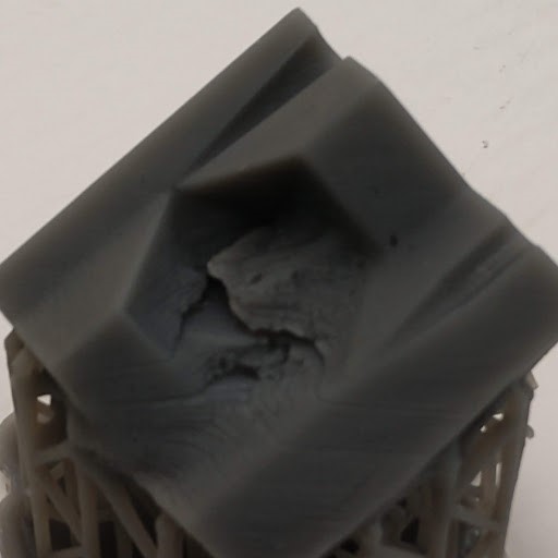
Ok so I got close yesterday the firs pic is the one i printed at .05 res with all numeral fillets removed set at a steep angle… I got the ejector pin hole I wanted but you can see some bad striations and some of the numerals didnt really come out. I tried printing again at .025 res and at a shallow angle "my thinking being that the internal faces are what i want to turn out the best, and at steeper angles one or more faces are closer to parallel to the print bed. anyway you can see it failed… I also attached a pic of a similar mold printed in flexible… I actually have gotten better results with the flexible than the one pictured, its all i had on hand atm. IT was printed at a steep angle at .025 res. Im wondering if i could use another material, like grey pro or tough if that would work as a mold, im using two part resin at warm temps, no more than about 100f so im starting to wonder if this just wont work with the high temp resin?
Are you sure the optics are clear? Looks like a print done on a fogged pdms.
Blobbing and distortions are also a sign or an under exposed resin which fogged pdms, clouded glass or main mirror can also cause.
I have no experience with high temp resin but I agree with @KenCitron : this looks like there’s an issue with the ammount of light getting to the part.
Have you tried printing this :
and looked at the result ? This .form file tends to exaggerate the issues related to the path of the laser and will help in telling whether you should clean anything. In all cases it’s a good opening point for a Formlabs ticket if you want to speed things up.
thanks for the Tips I will try out that print pattern.
before I embarked on this latest round of mold printing, I did clean the print window with PEC pads. It had a faint haze that I could only see with a flashlight. I also looked into the machine to see if I could see anything on the mirror “i didnt see anything” I have had many successful prints uning the high temp material before but this one really is confounding. honestly I’d love for a dirty mirror or window to be the problem. I have a print runnning right now but i will revist this when its complete.
I will advise when I have more to report, but in the meantime i really appreciate any ideas.
thanks
Close, but no cigar. this is the same file at .025res. i just set it at a steeper angle… I got ok resulds except for the distortion.
I checked the window and the internal mirror with a flash light. there was a some slight straking on the window but it was very faint. i cleaned it up but it was very faint. but the mirros are clean and i dont see any dust inside the printer.
I still don’t know why the surface looks so blobby. Do you really need 25 micron? I use 50 usually even with small text as most of the modes are at angles so your more reliant on the laser spot size and xy minimum feature size. Finer layers usually useful on very small objects. Build lines are not so bad on sla as compared to a polyjet system which usually have very evident build lines and tend to have ratty edges (because the resin is sprayed like an ink jet printer).
I’m not married to the 25 micron, but it seems to be the most successful of the various failures. I’m open to trying it. I was afraid of losing numeral detail
25 micron would be necessary if you had tiny features that were vertical on models orientation. XY resolution and feature detail makes up majority of the model as that doesn’t change on the printer and is determined by the laser spot size.
Well I tried printing this in grey pro just to see what happens, i also set the res to .1 mm. I also printed these little brackets just before the mold print with no problems same resolution as the mold test.
Im starting to wonder about the triangular hole in the print. Just for some backround… I printed this in flexible many times last summer with good success. I am also starting to wonder if the new firmware may play a part?!
The main print window seems to bave some faint “abrasion” marks for lack of a better word, where some kind of coating mmight be worn off maybe? but it is so faint as to be almost impossible to see withouth the aid of magnification. I also have printed may prints besides the mold with no problems… when i upload the mold to preform it detects no errors BTW.
The freaky thing is that it only appears to effect the faceted cavity.
If it were optical- then shifting the position of the print should change the location of the flaw… but the vents and separation planes appear to pint perfectly.
One test I would suggest is to post the actual model and let one of us try and print it to see if we are getting the same results.
That would at least identify if it were the model, versus your machine.
If other machines get a similar result- then we can know its model.
If only machines running the latest software have the issue then its the software.
I am still running Preform 2.17.1
PS- have you considered printing a positive model of the die and making a platinum silicone mold for casting?
yeah The model is still suspect… with that in mind I made some changes to my original this moring after my morning post. i dont THINK its a shifting model but who knows.
I am running 2.19 preform my old molds were on 2.17.1 as well
I printed this new part today with the small changes to the numerals, please note the buldge on the outside of the mold “this face should be smooth”. so this is another mystery. The setting is .1mm res
i had thought about printing a positive, but am hesitant because of the support poits being left over affecting the quality of the finisshed mold.
Ill post the file later once this post has some time to digest.
Hum, have you checked for cupping ? Are you able to share the STP file with Formlabs so that they can check if the file is good or not ?
I would still print the test print linked earlier. Your printer could still have optical issues and this print makes the laser pass several times over the same area to increase the consequences of such issues. It is also possible that that simple successful model you showed photos of could print successfully but the increased complexity of the letters in the dice mold as well as the possible cupping could lead to issues.
The model as you said might be causing issues. I would try to make a completely new file from scratch, maybe just with the shape of the dice without the numbers and print it with the same orientation.
By the look of your part, especially the last two trials, my money if still on low laser power (=pollution on the optical path, or dying laser but that’s unlikely and obviously not good news).
you can print a positive with no support points on the relevant surfaces.
Its call a split master.
So, imagine the opposite surface from your Die mold.
That would be a solid block, with its UPPER surface being the negative of the separation line in your existing model- and instead of a cavity, just HALF the positive die form sticking up out of that separation line.
As if you poured resin over the entire separation surface and cavity of a ‘good’ print of this die mold.
Your vents would show up as Positive forms sticking up out of the separation plane. And so would one half of the die as a positive model of the die.
For the opposite side of the die you produce a second inverted model- capturing one side of the separation plane and the other half of the die sticking out positive as a model.
You end up with two blocks you can print with the separation plane and each half of the die as a positive model. These can be oriented on the printer with the precision surfaces down facing and so avoid contact points and their inherent distortions.
You then pour a high durometer platinum cured silicone on each of these blocks- and when you peel the two silicone parts off- they will fit together and form a mold.
Platinum silicones can be found that have near zero shrinkage and they can handle the temperatures you plan to cast at.
The only reason for a rigid mold on something like this is if you plan to use an injection molder at hydraulic pressures.
Conversely- you could also use the Split master to cast a metal filled resin to make the mold halves- if you need to injection mold the dies.
wow, thanks for all the info thats allot to digest. unfortunatly I was hoping to use the high temp resin for three reasons.
durability of silicone molds wear out in this application
i want to polish the interior mold cavity to get a satin or hopefully close to mirror finish.
I want to prove out the concept of the ejector pin design I am using. the goal is to eventually have these concepts put into an aluminum or steel mold.
Im not using injection mold pressures, Im using a two part polyurethane at the moment. im hoping the molds i make here will be useable for a while so i can prove out all the concepts. I’m by no means an expert in this feild so im learng as I go. and perhaps in the future i can integrate these ideas into a small scale injection mold design.
I have to get the darn mold to print correctly first lol. Ive successfully cast lots of dice in my printed rubber molds, but that material has several limitations, and i want to move beyond this step. Im attaching the .STL file for this part feel free to give it a shot. i am going to run that test print today ,see what happens.
the settings i have had the best results are .025 res “the smear/blob effect sems to be the least pronounced with this” but I am sure a lower res would work. 6mm point size 4 mm above bed, default raft thickness. 30 degree or more part angle on all axis, I try to orient the part so there are no supports in the mold face or cavity as well as no supports in the pin hole… ive attempted to print this in grey pro, high temp and rigid resins. but i see no reason why it wouldnt work as a print test in any of the normal plastic resins as well… attached is also a pic of how i usually orinet my part. aagain thanks for all the help, i really appreciate it… I really enjoy this project, im hopeful i can get it to work out.
btw Do i NEED to use clear resin for the test print? I get that it would be preferrable but currently I dont actually have it on hand, im going to try it using high temp.
thanks
I have never used an engineering resin for this print, but I don’t see why it wouldn’t work. However results may not be comparable with prints done in standard resin.
I have often used Std Grey and Clear, but Black and White should offer comparable results.
Damn it. That doesn’t look too bad. I can’t see if all the straight pins and the trenches on the central piece are all there, which they should (except from the thinnest pin and trench which can not be resolved by all printers), but the pillars look fine. Getting larger in the higher number is normal and usually not worrying as long as detail is still there (number visible, edges sharp)… although when printing in Standard resins the increase in size of the pillars isn’t nearly as dramatic.
So that rules out optical contamination I guess. Left are low power laser (I don’t know how to test for that) and bad STL file.


