Optimising print supports: Form 4/L and engineering resins

I am new to the Form 4 and we are using it to evaluate the Form 4L as a production system for final parts. This post is a request for experienced people, especially including Formlabs staff, to chime in what I hope could be a useful reference on support techniques for:

  • Form 4 series printers
  • Engineering resins
  • Final production parts

I will state my personal goals for this kind of printing but obviously anyone else is free to provide their own preferences and context in the topic.

  1. Dimensional accuracy is a high priority. We need these parts to repeatably fit other parts, such as dowel pins, washers, bushings, sheet metal edges etc.
  2. Mechanical strength. We need to print / support / post-process in a way which will achieve full properties of the materials.
  3. Process reliability. This applies both to ensuring a high yield in full beds on a Form 4, as well as the success rate and ease of support removal by technicians.
  4. Material efficiency. The support strategy for production parts in engineering resins should seek to minimise the resin used in supports/rafts, to save money and reduce impact on the environment.
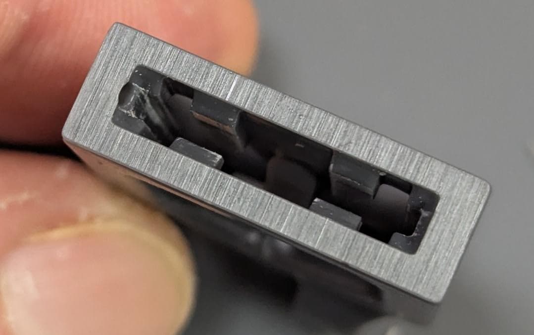
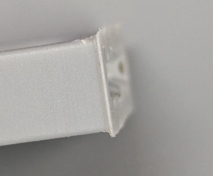
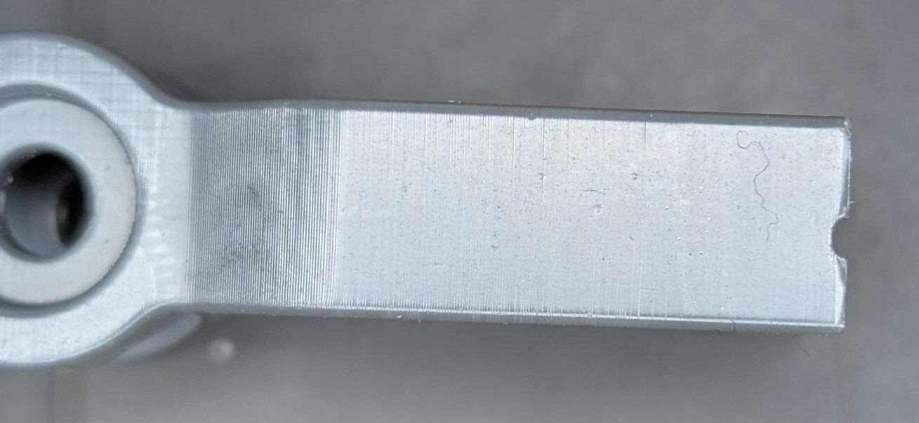
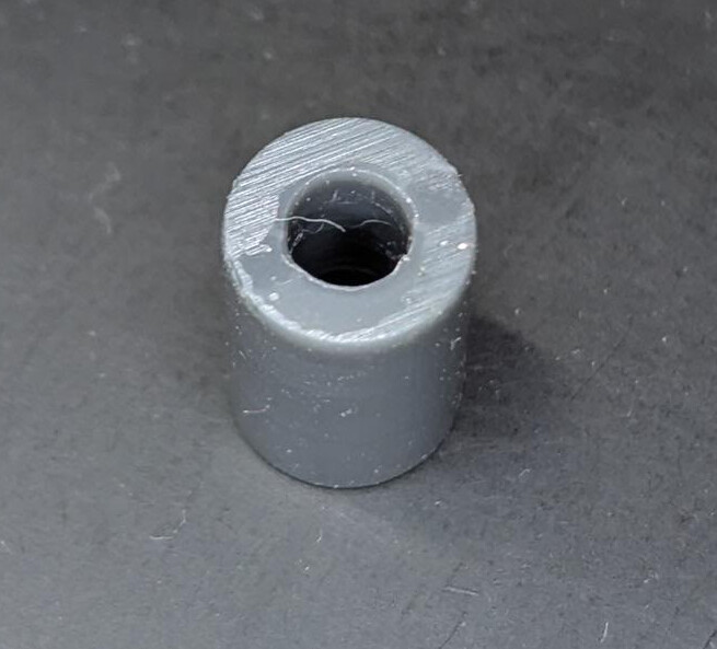
  5. A slightly lower priority is aesthetic finish. We can allow for support contact areas that are marred by support “witness marks”. However, if we can design to minimise the perception of witness marking, we would like to explore that.

So, here are the useful resources I have found so far:

The reason I think this is worthy of disussion is because I see videos of large full-plate batches of parts with minimal to no support structure, or very detailed support structure shown. Can the print optimisation experts help with this? Examples:


From optimum on YouTube (also featured by Formlabs in a Short, recently). Ali (the channel presenter) says he’s spent as much time tuning the support structure as the part, which clearly results in rewards as his parts look very clean once support is removed.
Notice how he appears to have continuous support around the scroll wheel rims and under the lower button surfaces.

In this Formlabs Short, they clearly show parts which do not appear to have massively high surface area against the build plate (relative to their cross sectional area further up the print) being printed reliably in large batches.


How do they plan this and achieve a good taper at the end of the black part? I get “elephants foot” when I print straight on the bed (as recommended by Alex McCarthy in the video above, and how I would like to continue to print). I understand that vertical compression and early layer unioning are part of the considerations when printing straight onto the build plate but it would be really helpful if the print optimisation team could provide more guidance on how to factor this into design and slicing. What rules of thumb are there about e.g. build plate contact area vs cross sectional area of higher layers? What adjustment to the first millimetre or so should you make to compensate for the higher curing levels needed to ensure good print adhesion?

I’m sure there are tips scattered across this forum but from my search about support strategies for production parts haven’t found much. Hoping this is also of interest to @revel and @jessbuck following their recent discussion.

1 Like

I make a bit of content on my YouTube and Instagram showing parts of my workflow for optimising supports.

Working on some more in depth videos and tutorials but they take a lot of time.

We also have a blog post on the Ember Prototypes website that has some useful tips.

I also gave a talk at last year’s user summit about pre processing and post processing tricks. Link to it is on my blog and also on the FL YouTube channel.

Maybe some of those will help but always happy to chat further.

2 Likes

OK, @leonhart88 your video was one of the reasons I thought we could make this shift, so thanks for putting your stuff out there! Now I can connect the dots!

Your videos are great and I didn’t know the recent Shorts, which are cool and directly relevant to this topic. For a start, you’re giving materials and settings. The bonus is that you show the results and talk about the effort that goes into support planning.

Definitely worth including in this thread!

1 Like

Happy to help and share my knowledge :slightly_smiling_face:

2 Likes

Testing Continuous Support vs Conventional

I started experimenting with adding custom support in CAD and printed a comparator in Tough 2000 with a face on the bed and three Preform supports to address the warnings. On my presupported model, I made 0.2mm “rails” around the rectangular base (the face I placed downwards). I made sure to add a bevel to the raft to make sure I could catch the edge of the scraper under it and I made sure that there were holes to the central void to prevent a suction cup from forming, as well as allowing better washing.

Slicing

The job settings were 0.1mm layers, with Default print settings. I deliberately ignored the support warnings on the presupported model, as I was confident it would print properly without.
How they looked in Preform:

Results

The presupported part printed fine and was easiest to pop of the flex build plate, because there were no disconnected support bases to worry about (long and rigid connection, so easy to pop because I aligned it across the bend axis of the steel):


However, the results for post processing and finish were not good.


In contrast, the part I placed straight onto the bed with a few manually generated Preform supports was very good. There was minimal “blooming/overcure” around the edges of the face on the plate. In fact, taking into account that Preform automatically extends the cross section at 0.75 mm height all the way down to the build surface (effectively negating angled edges caused by chamfers and fillets):


(PS, you can see the 45 degree hole I added to the bed-mounted part to prevent suction cupping)

Discussion

Now this somewhat surprised me because the reason I had been concerned about direct printing on the build plate was due to prototypes I had printed in Grey V5, which came out with significant flaring, even when the walls were vertical and the effect of the “early layer unioning” (ELU) was irrelevant. Note that on the Tough 2000 parts, I do have a slight fillet around the outside, whereas on this V5 practice part, the walls are vertical to the bed:


So there’s clearly a difference in the approach to curing the first few layers of Tough 2000 and Grey V5. I am happy that Tough 2000 is better, as this is the material I want to use for production, but at half the price, I prefer to prototype in Grey V5 and it would be nice if the parts came out dimensionally equivalent for a given slicing strategy.

Lessons

  • Tough 2000 was pretty good straight onto the bed. Due to the success of the unsupported upper half on my presupported model, I might try printing straight onto the bed without any support.
  • Presupport bevelled rafts are great for print removal from the flex build plate.
  • My presupport also produced a successful print without noticeable defects, despite Preform warnings.
  • The anti-suction-cup holes in my presupport meant I didn’t need to put a hole in the part.
  • My presupport didn’t break away cleanly. I need to improve this if I do it again. 2 ideas: make the transition to thicker material steeper, so it concentrates stress against the contact points and reduce the rail contact width to either 0.15 or 0.1 mm for Tough 2000.

Conclusion

I think there’s a lot of potential to improve the way production customers exploit Formlabs SLA and draw people in as customers. I thought it was possible partly because of the videos of @leonhart88 and Formlabs themselves. But the corporate flashy Shorts are not the deeper level content that serious customers need. We need more guidance, videos, blog posts, forum posts from the likes of Alex McCarthy and his team. It is clearly model and material specific stuff, so even acknowledging that and explaining an approach to help people find their sweet spot would be great.

2 Likes

We’re working in full production on the Form 4 platform. May be moving into 4Ls as well here shortly.

Primarily running Black V5, and quite happy with current iterations.

All in all, we run anywhere from 200-600 parts in a given week-usually 40-50 up on a platform. Keeping the parts VERY close together (>3mm separation between adjacent parts) allows build density, lowers total build time and cleanup hassle.

A couple of points we’ve seen.

  • keep on those firmware updates. Somewhere recently, some support bracket management got updated, and our support quality went up. In fact, the only way we’ve been able to have a print fail now has been when we fiddled with print settings (see elsewhere for my multiple failed attempts to run Black V5 at .200mm print thickness - TLDR>bad idea, don’t fiddle under the hood, it doesn’t help).
  • smaller touchpoint size translates to much fewer surface imperfections. We have many parts which don’t get ANY post-production clean up - just pop the supports off, and wash them!
  • taller parts generally DO need more support points, and more so, depending on the height.. some 7.5" tall parts actually need a lot of points, when you downsize the touchpoints.
  • we drop height above raft to 2.00mm on almost everything. This is helpful (I think) in product release from the head. In fact, with a good setup, we don’t even remove the head from the printer during production - simply reach in, pop the flex a time or two, and catch the product. (This works best when all your parts are on a single raft, so you can separate later).
  • thinner rafts save time and resin, but going TOO thin can result in a lot of challenges with head cleanup.
1 Like

It’s fairly easy to solve that elephant foots problem with the print settings editor - see this link

As you determined empirically, different resins and settings will behave differently.

Also - I bet you don’t need supports at all for this part. I would print it straight on the build plate as you did but delete all the supports. If you step through layer by layer it can give you confidence that this would work - regardless of what Preform says.

I’ve been meaning to make longer form videos showing some of my process…it just takes a long time and I don’t get paid to do it - but trying my best to share as much knowledge from my head as I can :flexed_biceps:

2 Likes

Thanks for this insight. I am definitely in the camp of starting with default and only doing conservative tweaks. But I realise I won’t find the edge if I don’t push a little bit.

Thanks - I think this is probably what the Optimum Zero mouse shell/frame is made from. I selected the grey for prototypes because it has slightly better mechanical specs over the black, according to the spiderweb diagram on the materials comparison pages and my small parts aren’t colour sensitive.

Do you remove these dense parts from the build plate and wash them in the basket, or wash on the build plate?

I second this. I also at this early stage am orienting the parts with the raft or contact surface across the bend axis of the flex plate, so that it really encourages separation when bent. When the long edge of some narrow-contact parts has been parallel to the bend axis, they have not popped off as readily. May need to revisit for the best part nesting but I think I’ll keep this as a rule of thumb.

Impressive!

Thanks, I hadn’t seen that option before. It should work on the Grey V5 with vertical faces coming off the build plate, but I don’t think it will deal with the Early Layer Unioning for chamfered and filleted corners touching the build plate, will it?

Perhaps not. I was a bit unsure as the cross-sectional area further up increases above the surface attached to the build plate, but perhaps the LFP helps manage that. TBH, the supports I had don’t really kick in until the print is past that point, so you are very likely correct!

Thanks for that link - yes - very valuable.
We have several part sets which we print without any build supports - just printing directly on the surface.
Several advantages:
a very nice finished surface (minus the elephant foot issue, though it’s easily resolved)
faster build (less support build time)
easy part removal.

We’ve got one small part which is 164-up on a form 4, VERY tight pack (about 1.5-2mm) separation, in numerous rows. These are printed on a VERY small flat edge (~ 2.5mm x 16mm flat edge), and we’ve not had a single failure out of > 5,000 units produced. VERY reliable, and needs no post-production clean up (aside from wash).

About washing/cleaning:

So we have 3 wash systems: a 5 gallon system we have developed ourselves for bulk pre-wash using SG (Simple Green) concentrate, a separate FormWash unit with SG in it, and a Formwash II with IPA.

When it comes to production, we drop the entire support raft & parts into the 5gallon SG wash, where it ruminates for 5-10 minutes, then we pop the parts off the raft and place into the Form Wash. This has cut a good 50% of the resin off the parts prior to the IPA, so our IPA lasts tremendously longer.

With short supports, close tolerances, and thin rafts, we rarely have rafts stick to the build plate. So with a build raft that covers 95-98% of the build plate, popping it loose is VERY easy with the flex head - just wiggle a time or two and the whole build pops off.. using this route, we have to remove the head only 1 out of every 8-10 runs. Which saves a lot of time & hassle in production.

The longer supports SEEM to make parts removal a bit easier on occasion.
But the longer the supports, the more flex, and then thinner rafts will tend to stay stuck on the flex head…

1 Like

Early layer unioning is a parameter in the supports fly out within Preform, so you can adjust that as needed along with the elephants foot compensation method.

Ideally elephants foot compensation is actually in the support flyout in Preform rather than in print settings. I’ve raised this to the Preform engineers but we’ll see if/when that gets implemented.

2 Likes

It’s really helpful to hear details on your workflow. Thank you. I am wondering what the waste stream looks like for the Simple Green with resin mixed into it. Is the SG recoverable? Could you please shed any light on this or its disposal? We are looking at a solvent recycler and probably a 2nd stage of IPA prewash/sluice but I am intrigued by your multisolvent process.

Interesting. I will definitely weight that one up. I currently suspend the flex plate by one of the paddles on the mounting point for the whole plate when a build is finished, just to let resin trickle to a corner and dribble off back into the tank. I wasn’t doing that initially and that’s probably contributed to my IPA clouding so quickly.

Interesting, thanks! I don’t remember seeing it was controllable in the support article.

I did a separate writeup about our multi-stage cleaning system.. i actually left 2 steps out in the notes here, in an attempt to keep it simple.

We focus on production. Yes, there’s testing/prototyping, but once a part is locked in, it’s loaded full-up on a plate, and run. sometimes we run the same build (say 50 parts on a plate) for 20x’s without stopping… so we go thru a lot of resin - usually 10 liters/week (we’ve got several form4s).

So, the issue with workflow isn’t just “saving IPA” - it’s a huge time savings.

  1. SG is $8/gallon at Lowes. IPA is ~ $20/gallon on AMZ.
  2. we don’t like the idea of dealing with loads of IPA to ‘get rid of’, from an ecological perspective, and we also don’t like to have to recycle a lot, so we hacked up a recycling system off a whiskey still from AMZ.
  3. This still requires a lot of time (to recycle) - it can take most of a day in the background to run 3 batches of 10 L of IPA thru the still, and even though we do it while running other jobs, it’s an annoyance..

About SG - we’ve not YET (13 months in) hit a point where the SG can’t be cleaned/dried out, and reused… it’s slightly less effective, AND it takes a while to ‘dry out’, but it’s been cycled repeatedly.

To ‘clean’ the SG, we pour the ‘used’ into a tall/narrow jug (to speed up gravity separation), and leave it in a dark corner for 3-4 days. The resin settles to the bottom and gets very grey.
Then we take the jug of it out, leave it on the dock for a few days to harden in the sunlight.
After 12hrs in the sun, it can be slowly poured off the top, the ‘sludge’ in the bottom is then poured out into a pan, left to harden in the sun, then it is handled as an inert plastic.

So, current work flow:

  • Pop off entire raft with product. no separation or hand-cleaning.
  • Drop entire raft into our 5 gallon SG wash system.. 10-20 minutes (depends on what else is in downstream washes)
  • Pull raft out of SG bucket, pop parts off into FormWash with SG. Formwash SG runs 10 minutes.
  • Shake off excess SG into FormWash, then ‘slosh’ in & out of a “dirty” container of well-used IPA (primarily to remove excess SG prior to final IPA wash)
  • IPA wash in FormWash2. 5 minutes
  • Shake & drip-dry - 3-4 minutes in room temp.
  • 3 minutes in Form Cure.

This minimizes the amount of wear on the IPA, product comes out clean and dry, and we are able to make 30L of IPA last about 10 days prior to running thru the recycling system.

2 Likes

I support this topic - available materials on the topic are needed. Maybe I haven’t been looking in the right places, but the support articles don’t scratch that need. Looking through years of forum posts where some support videos are scattered is not that simple.

Developing a sense of what works through trial and error could work, but the process of dealing with a failed print feels much more of a hassle (not particulary keen on fishing out cured bits out of a resin tank) than it would be with FDM (wiping spaghetti off the plate). Right now, I’ve limited myself to making just the following changes:

  • ~40 degree incline
  • Reduce cross-sectional area/sudden jumps
  • Rely on auto-supports, sometimes remove a couple of points in bad places
  • Adjust touchpoint sizes as per Ember Prototyping guidelines

If I’ve missed something or someone has tips to build up a sense for the process, definitely let me know!

2 Likes

Update

I followed @leonhart88’s encouragement and tried printing my test part without any supports. Although the support warning was present in Preform, I knew that I had designed the part to have gradual profile changes and no overhangs, so a cursory glide through the sliced layer visualisation was all I did before printing. The part came out completely fine. Still had potentially minor elephant foot (original was almost none, compared to the Grey V5) but this is something I can work on in slow time as it doesn’t impact the part in its final application, at the moment.

1 Like

Awesome! Gliding through the sliced layers is something I always do to make sure I have the rights supports in the right places. All this pre-processing takes time…but it generally leads to less cleanup and better parts in the long run.

Editing the early layer exposure & offset in the print settings will 100% solve your elephant foot problem. I had to do this with Clear resin on the 4L. My settings ended up being something like the below. This being said, if you are designing your own parts, you can always just add a chamfer to that surface. I don’t have this luxury most of the time though.

If you guys aren’t following me on Instagram or YouTube, I recommend it - I post a lot of stuff on there :slightly_smiling_face:

2 Likes

Update - adjusted Early Layer Exposure and Offset settings

I have been meaning to try this for a while, after @leonhart88 suggested it. It has taken me a while to find the time to do it, as well as building confidence that the stock exposure settings were definitely going to work without supports.

My setup is Tough 2000 V1.1 resin on a Form 4. I had no idea where to start other than the screenshot above, especially as this is for a different resin. However, the two main things I did were

  1. Add third row between 0.00mm offset and 0.50mm offset, at 0.10mm offset
  2. Tweak the Offset column value for the 0mm and 0.1mm rows. The default was a strange -0.007 or similarly insignificant value. I went to something like 0.3 (positive increase results in less elephant’s foot, which might seem counterintuitive) on the 0mm and a different value for 0.1mm.

You can see my new profile attached if you would like to try it yourself.

20251016_Tough2000V1-1_print_on_bed.fps (140.0 KB)

.fps File (Print Settings) Community Library . Compared to my previous effort using the stock setting, this has definitely made an improvement.

The “half” holes to prevent cups are one of the ways I can tell the bottom 0.5mm has improved. The cylinder is 6.5mm OD, for a scale reference. I had no issues with fit or clearance on the inner diameter (obviously I have some tolerance but I’m happy). The edges are square enough. Perhaps even a tiny bit chamfered. But I’m happy there’s no elephants foot and I have printed a quarter flex-plate of these and nothing failed.

1 Like