It seems to be a capacitive sensor, also called a dielectric sensor. It works by detecting changes in the dielectric constant of the surrounding area. It may sound complicated depending on your background but it’s really a standard and simple device. I am no electricity expert so I wouldn’t be able to explain in details how the sensor works but I do have some amount of experience using them.
Because of it is a simple device it is binary in its function : it can tell if it detects resin, or if it doesn’t detect resin. As such it only knows it the resin is above or below a certain level and it cannot know what type of resin is in the tank.
The main downside of these sensors is that they often have a pretty limited range, often not much more than a few mm. So if the sensor is clean, and the tank’s exterior too, it may be that the positioning of the sensor is bad on your machine (from my experience it is the most common cause of issues with capacitive sensors in the industry). It could also be that the calibration is bad but that’s unlikely especially if the sensor worked before.
As for wiring they have usually 3 wires. Positive, Ground and Signal. The exact voltage required and the nature of the signal output varies a lot depending on the size and quality of the sensor.
Thanks for your reply ! Sorry to reply after 18 h . We have done some works .We opened machine finally.
we have found the wires of the sensor connecting to the PCB but it has four wires, red blue white and black.Maybe there’s an unusual sensors in my machine ,
I wonder if I can sove the problem by replacing a new resin senor.
And I tried to clean the board located the sensor but it didn’t work.A spot cannot be removed by isopropyl alcohol . I didn’t touch the sensor,but board.
Formlabs sold a bunch of machines that were plagued by a raft of resin sensor errors.
After a lot of complaints- and a lot of checking to make sure we all weren’t doing something wrong- Formlabs determined that it was a Grounding error in the sensor- that a whole bunch of machines had had the resin sensor improperly installed.
There are four allen screws holding sensor to the pillar- The lower Two of these screws can only accessed thru holes in the rim of the tank carrier- when it is in a specific position.
We were instructed to get a weird 1.3mm size allen driver - and to LOOSEN each of these screws- and then re-tighten them ONLY moderately hand tight.
For mine- I found it took quite a torque to get them loose- they felt like someone had Way over tightened them.
Once I had re-tightened the screws with less force- the resin sensor errors ceased entirely.
I did an electronics project a while back that played with capacitive sensing and learned a little bit about this stuff. Someone told me the Form 2’s (at least the early prototypes) use an FDC1004 chip for this function:
There are some technical documents at that link for the not-faint-of-heart.
This doesn’t have any direct bearing on solving your problem but I thought the background info might be interesting to anyone else here who’s curious about this stuff.
Hi ,bro 。
I’m sorry to bother you about the seneor and its board.
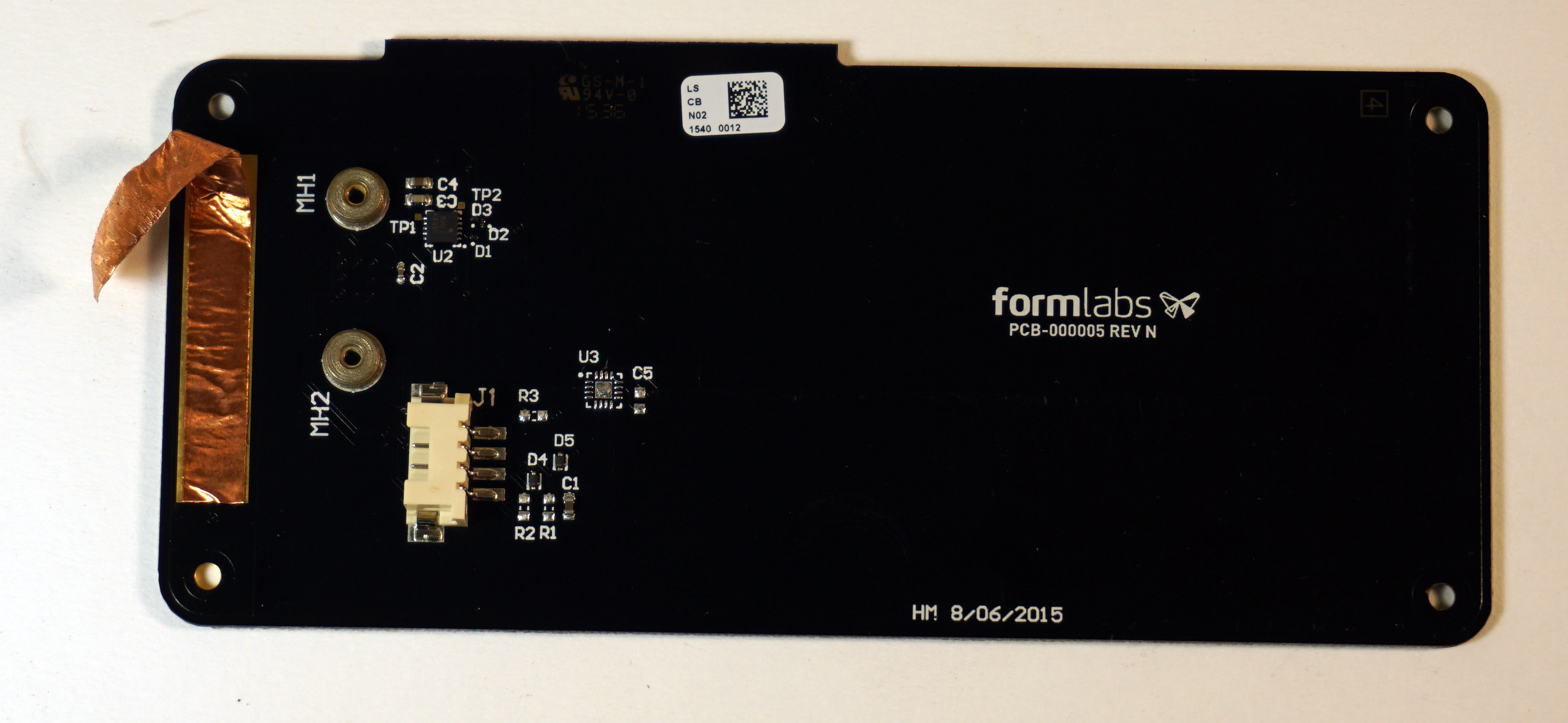
we have read informations about the sensors.And have no idea about the how the Chip and sensor connected. CIN1 and CIN2 were connected to the MH1 and MH2
or not.
We check out the back of the board founding that the “camera” ,the sensor’s probe has several pins . And it’s dirfferent from your pictures .
Maybe the four pins are just localted the sensor on the board or it should be connected to the Chip
FDC-1004. I wonder the probe was moved in your picture and what we see is just two metal rings that is just the foothold of the sensor probe.
As an engineer, I understand the desire to dig into the system and figure out what’s going on, but our support team will be the best way to get you printing again, and there are parts of the system calibration that could be thrown off with too much disassembly.