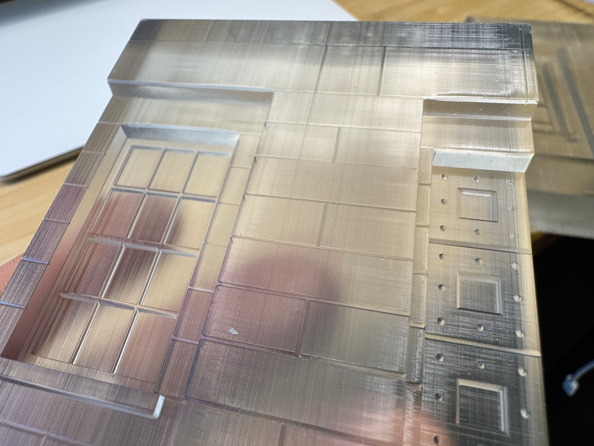
This is a small part of an architectural model printed on a Formlabs Form 4 using Clear Resin v5. Those vertical lines are deep enough to feel with your fingers. I’ve printed it 3 or 4 times now, and all the prints have it. I even tried turning it 90 degrees, and it still has those same lines in the same direction. I printed it with a grey opaque resin and those lines are not there. Because of size of the final parts, they are not printed at an angle, but with one of the sides flat against the bed.
What can be causing these lines and how can I fix it?
One thing I noticed in your .form file is that the printed part is standing upright — meaning its length runs along the layer stacking direction. A lot of times when I print parts like that, the layer stacking doesn’t come out “perfect,” and you end up seeing lines. I can’t guarantee that’s the issue since our machines are different, but I’d recommend trying to print the part lying down.
You even mentioned that you tried rotating it 90 degrees and the lines were still there. I’m guessing you left the part supported along its width to avoid the “cup effect” that shows up when you place the part lying flat on the build plate. Honestly, if it’s just one piece you need to print, I’d try printing it with a small hole on the side like in the image below or even without any holes.
Below I tried to represent this imperfect stacking of layers.
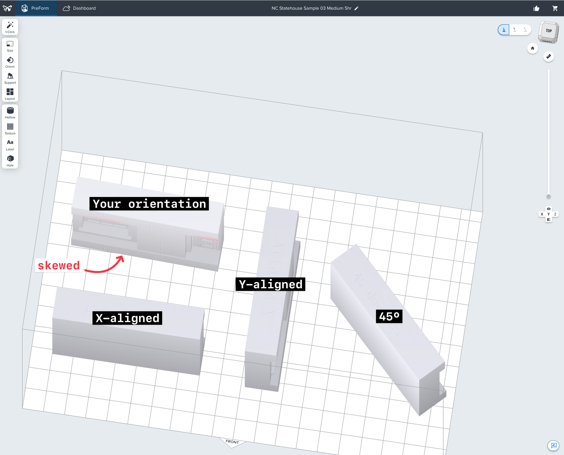
Hey @jbhaas, it looks like the model in your file may have been accidentally very slightly skewed off-axis. That kind of subtle misalignment can expose some of the pixel-level “stair stepping” artifacts from the voxel-based exposure process we use, especially in Clear resin, which tends to refract these effects more than opaque materials like Grey. This isn’t due to the printer malfunctioning, it’s a side effect of how we digitally approximate smooth geometry using discrete pixels in the exposure engine.
I ran a print of your model using the exact orientation from your file, plus a few variants: one axes aligned (X or Y), and one tilted ~45°. Aligning the model perfectly to one of the primary axes (X or Y) significantly reduced the visible ridges. The 45° orientation can also help, but introduces other structured patterns. Something like 30º would do a better job at breaking those up, but if your model is square (like yours), aligning to axes is your best bet.
Your skewed model: Same voxelization you were getting on your part. The pixels on the LPU are almost “stairstepping”.
Axes-aligned: This one was aligned to the Y axis, but would look the same with the X axis. Significantly less repeating patterns like the skewed model.
45º:better than the skewed model but still introduces some artifacts. I learned after starting this print that 45º leads to a very structured pattern still. Something like 30º does a much better job breaking up structured patterns.
In your case, your mesh had baked-in model coordinates that made it easy to reset orientation properly with the “Reset Selected” button in the Orient panel. TLDR: Square models like yours will have cleaner flat faces if you align them to the printer XY axes. Hope this helps!
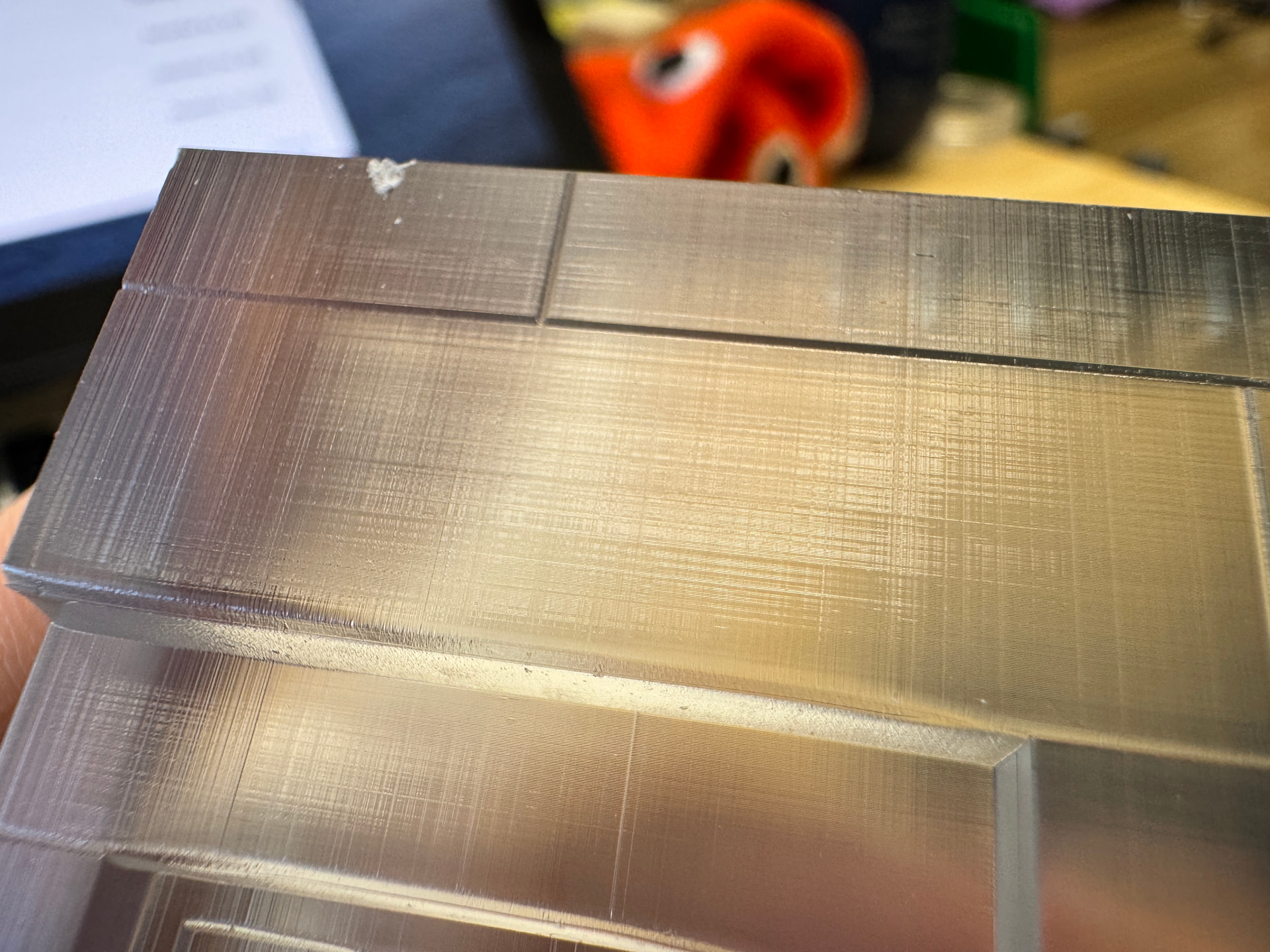
These images are macro shots that make it easier to see what the original poster was trying to diagnose. The Form 4 has dimensional accuracy within ±0.15% (lower limit of ±0.02mm). Clear parts can also exaggerate tiny surface details because of how light refracts through it, but can be post processed with polishing, or clear coating.
Here are a few more of my favorite examples of Clear Resin being post processed: