There will always be marks from where the supports touch, but if I understand correctly, the “wave” you describe will be greatly reduced if you orient the part so it is more vertical. As it is, as the part is printing, it is spanning out at a fairly shallow angle when it is between supports. If it is oriented more vertically, that effect will be reduced.
The issue is due to how the laser will go through the resin beyond the current layer that is printing. Resin sticks to the outside of the print and that means that the laser will cure extra material on the downward facing surfaces. Black resin has a reduced effect since the black pigment blocks the light better, but all SLA printers have this issue.
for that type of thing, you can do as described above, if you angle it more vertically then you won’t need as many supports and there won’t be as much downward facing surfaces which will give a better result though at increased print time.
One of the things you have to keep in mind when designing a print is how you might orient a piece to get the best result. For example sometimes I split pieces so that details don’t face downward.
I really struggled with those on some of my prints as well. It seems to occur the worst when parts or projections are close to horizontal. I don’t know that it is actually caused by the laser curing a greater area because if there is a sharp edge they are only sharp at the point where the support touches and then there is a concave shape that extends to the next support point.
To work around this problem, I now place all supports manually. In my opinion the auto support feature is close to useless and does not produce the best results. Since the supports are there to counteract gravity and lift the printed layer off the build trey, they must touch the first layers that are printed. If a support starts above the first layer there is a good chance that the first layers will not peel off the bottom of the tank and you will end up with many failed prints. The auto support feature often places supports above the first layer.
I have had the best results by orienting to the bottom view and then placing supports manually as I step through each layer with the page up key.
To minimize the wave between supports, use more supports. I set the point size to the minimum and typically use twice as many supports for these areas as default. Again, make sure the supports are on the first layers printed.
I find the supports break off easily and I then finish the models with progressively finer nail files. I believe the finest is around 1500 grit. It’s more work but the results are unmatched.
As for the automatic support generation, sometimes it can seem weird where the support goes, like it’s not quite on the bottom, but if you look at the supports that are generated then it probably intersects the bottom anyway.
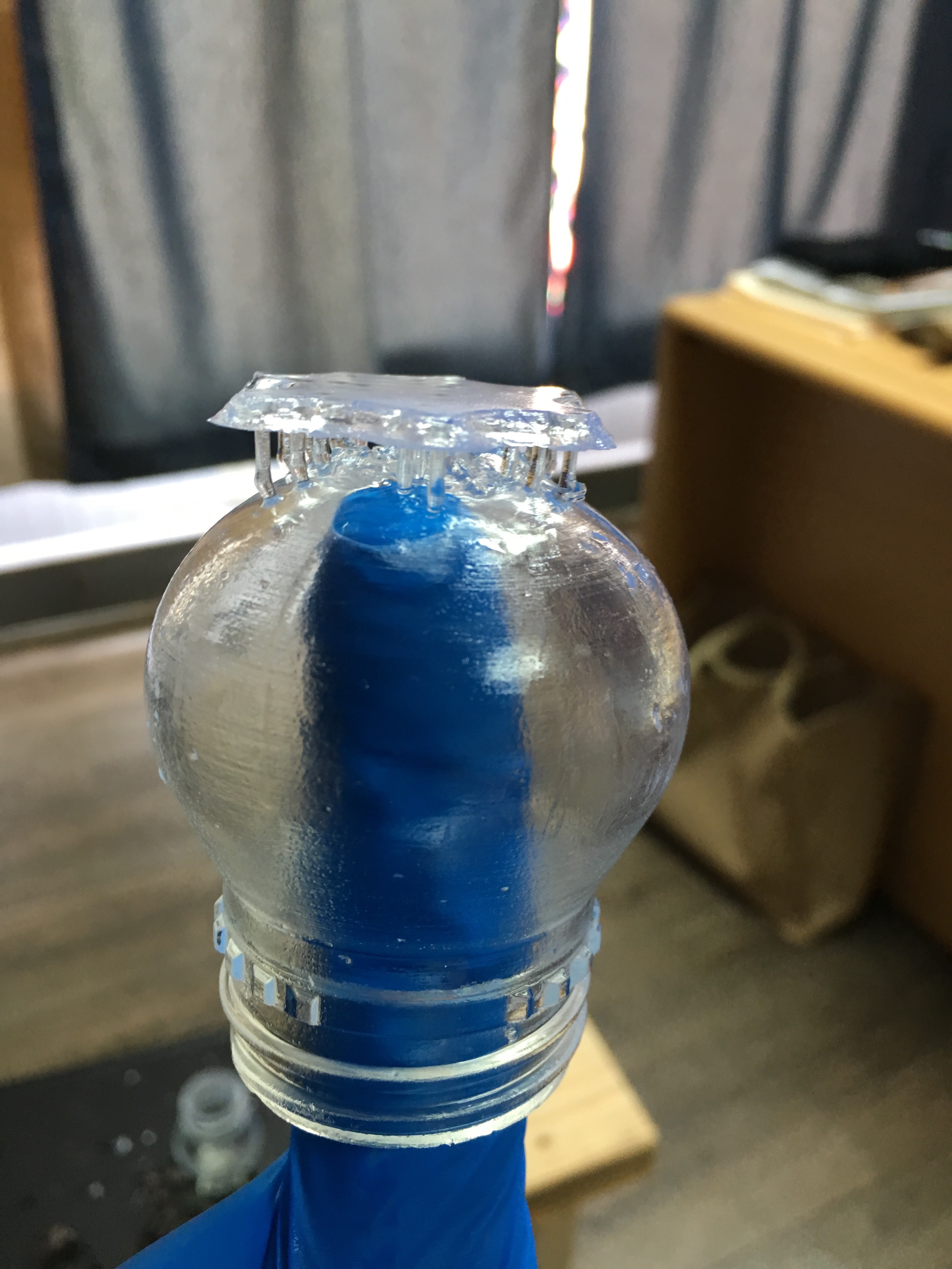
I will have to say the roundness of the bulb (trivial feature for testing) came out pretty clean and the threads were immaculate. That is the main feature we are trying to prototype, whereas the bulb is just a very small amount of material to create an enclosure instead of a full bottle
In this trial, one of the bulbs ended up with a hole or two on the top where the resin was soft and I pulled the support structure too hard. I also drew the bulb in about 2 minutes so I used a flat bottom so it would sit upright. Then I oriented the ‘bottle’ to drain directly down, which is why that flat section did not solidify adequately. However, sacrificing the rounded section allowed the threading to come out spotless with no structural support needed.
I’m doing graduate research in radiation semiconductor processing so I plan to adapt some of my sensor photolithography techniques for post print finishing. I will try and offer up any advice I learn along the way, but for now some quick tips.
Make sure your designs are logical for printing. Our parts are small and are going to be injection molded / blow molded so they translate very well to this type of printer. They are not too thin or thick in any specific area.
Orient at an angle! We draw in XYZ so we tend to use faces along these planes. Placing your part at an angle makes sure most surfaces will sit slightly off axis and you will have adequate drainage.
Open ends should point towards the resin tank. I pointed the bottle straight down and sacrificed the top of the bulb which goes against the previous bullet. Had I chosen maybe a 10 deg offset from vertical, the base would have printed more effectively and I would have still seen ample drainage. On the associated cap, I placed them at an angle with the opening pointing down and they were spotless.
Use the auto-support system. I found if you orient your part right and use just enough support density, the first part layers will build correctly and the part should grow successfully from there.
Consider the part thickness. Thicker cross-sections will not see as much oxygen due to a lower surface area/volume, so they will take longer to cure. It also means they are going to be weaker, require additional support, and should not themselves be used as a support for a feature hanging below.
I will add more to another thread on the support about finishing. I am going to build an overkill but cheap UV system. The end goal is to use the initial system to cure parts that will then be bolted on with a micro controller system as upgrades. Should be a fun learning experience!
I actually get the same detail with the clear without the hassle of the pigments settling out. Only difference between the pigmented resins and the clear is they add pigment to them. It has no effect on the detail of the model, just appear more detailed because you can see it.
You can use Silly Putty to take impressions of the models and compare, I use Silly Putty to check the surfaces and details prior to mold making to make sure my parts don’t have any blemishes.
As your tank wears and the PDMS gets clouded the waves on low angles may get worse.
If you look under a microscope 20X to 32X, Clear resin has sharper looking corners than gray and black. It’s just that you can’t see small features in the macro scale with clear due to its transparency and glossiness.
From the prints I’ve done, small details are noticeably sharper in black. There’s cases where parts that are close together end up having resin cured between them most likely due to the laser diffusing into the resin. I’ve also found that downward facing surfaces and places where supports touch the print end up with a larger amount of bleeding in clear resin. Most likely with clear there is less diffusion due to not having pigment to bounce off of, but it also doesn’t stop the light from going further through the resin which makes the bottom surfaces worse.