Printing model made of thin walls out of 80A resin

Hi,

I have limited experience with printing flex objects so, I am looking for advice on understanding what I could do to improve the quality and dimensional accuracy of this print


What really matters for me is that the ellipsoidal hole is reasonably dimensionally accurate (I need to insert a part in there) and that the walls of this part are roughly what the model says they should be. The walls of the ellipsoidal hole are 0.6mm thick and most other walls vary between 0.6 and 0.9mm.

Sadly, when I print this with the “magic” button, I observe two main problems:

  1. the walls of the ellipsoidal hole are 0.8mm in locations marked [1] and [2] instead of 0.6mm everywhere else
  2. the wall at [3] is super thick (2/3mm)

I tried to invert the orientation as follows but this only made the location [4] thick

Screenshot from 2022-11-26 19-12-29

I could spend a lot of time and resin (6 hours per print/10 to 20ml) to try a lot of combinations but I am looking for advice on how to orient this model and what parameters to select for support generation. Any idea ?

Also, I noticed that after after printing/cleaning/curing, I need to wait a while until the piece cools down and relaxes to its “true” shape. Is this a common issue ? How long is it supposed for a part to be “complete” after curing ?

I would lay the part down more, so that there are no supports in contact with the top surface of the print, they’d all be along the bottom edge and the interior surface. Since the hole that, I’m guessing something like a track ball protrudes through, is what you care about the most, I’d make it so that feature was parallel to the build plate. Then, I’d increase support density to 110%.

Positioned like this, maybe (the build plate would be below)
:

Hi all,

Randy’s suggestion for the model orientation looks good! This should optimize for the dimensional accuracy of the hole. In general, we recommend printing Flexible 80A models between 19-45 degrees from horizontal (see Using Flexible 80A Resin), so this could be another option to try if printing horizontally doesn’t yield good results.

Regarding your question about the part relaxing to its true shape after post-curing, I’m not quite sure how long you should have to wait. I’d imagine that flexible resins are more prone to this type of temporary deformation due to being heated during post-curing. Leaving the supports attached during post-curing, if not being done already, should help mitigate against any warping during the post-cure.

Hi Jesse, Randy,

Thank you for your feedback. I tried your suggestion: it was indeed extremely effective to make the vertical edge around the hole a consistent accurate thickness of 0.6mm.

However, this shed light on another problem: the horizontal thickness of the part around the hole is also incorrect: up to 0.9mm instead of 0.6mm as specified in the model.

Here is a picture which highlights differing thickness on the vertical edge and the horizontal edge:

The model displays constant thickness across the edge:

Screenshot from 2022-12-01 16-09-34

Because the part is expected to be assembled as shown below, it is important for me to make sure that the thickness is consistent around the hole, on both sides of the edge

Screenshot from 2022-12-01 16-59-25

So, what could I do to make the thickness on both sides more uniform ?

I have not tried the following orientation but I am suspicious it will not help:

Screenshot from 2022-12-01 17-05-19

I have not yet tried to manually layout the support contacts to avoid the placement of support points along the edge but I am worried that doing this would not help.

I have not yet tried to introduce a gentle orientation slope on the model because I am worried it might solve this problem but re-introduce the non-constant thickess of the vertical component around the edge.

I could change the shape of the model if needed to introduce a slope to make the horizontal part not horizontal and/or to make replace the square edge by a rounded corner. If so, how much slope would be needed ? How much roundness would be needed for the edge ?

So, my question is: what should I try next that, in your experience, is most likely to improve the end result ? Any idea I did not think about ?

Thanks again for your feedack,
Mathieu

Hi @mathieu_lacage,

Thank you for your thorough documentation of your testing so far. Horizontal inconsistency could potentially be the result of optical contamination. In order to narrow this down further, I would recommend getting in touch with our Support Team for them to review these photos, the .form file, and your printer’s diagnostic logs.

Hi Jesse,

Thank you: I have submitted a request to support with a pointer to this thread, the form file, and the printer logs.

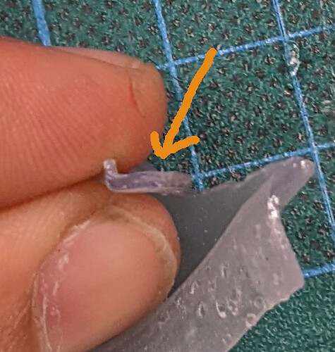
Another question that came to me is related to the upward edge of the part:

As you can see, the edge is jagged and, in at least one location, it was so jagged that it started to shear. I suspect that this is due to the supports that were all over the edge. Is there something I can do to avoid this problem at the model level or should I manually position the supports myself ?

Mathieu

Hi Mathieu,

I would share this additional information in the support case you have created if you have not already, as the form file will help give the team an idea on how to set this up better for you.

Based on what I am seeing at a glance, extra/manual supports would not be a bad idea since it looks like there may be a lack of supports causing the jagging.