Hi, first time form owner, just got my form3 and LOVE IT.
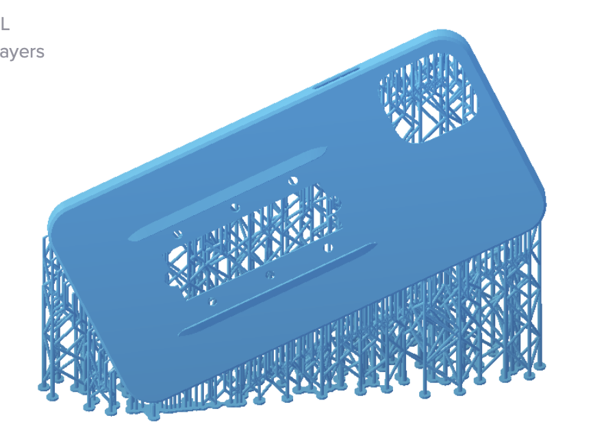
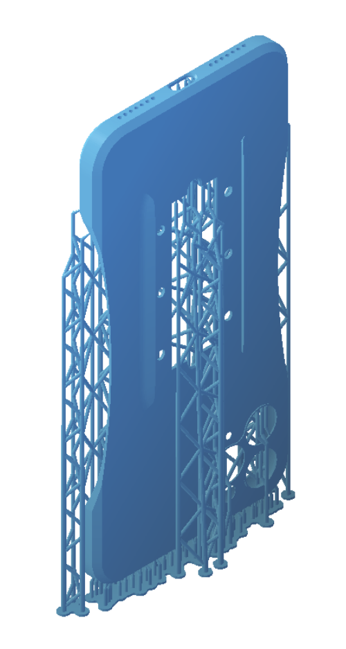
I’ve been testing different part orientations for various reasons. But lately I’ve been printing phone cases using the tough material, and it prints well when the part is oriented at an angle on all 3 axis. But it leaves a huge lattice structure that has to be painstakingly cut away. So I tried one print with the case standing straight up. It uses way less material, is faster, and way easier to clean up at the end.
However, it printed with this weird wrinkle in it, and I’m trying to understand why that is - and if there’s anyway to account for this. I read all about cupping that could cause this, but I really don’t think this part has that issue because its quite thin and only 3 sided.
I’m printing on full raft, and used auto-supports for the vertical print.
And Zachary_Brackin explained that tall thin parts can “wobble” if not supported well enough. Which makes a lot of sense. I guess I can just add more support to prevent lateral wobble on the next print.
In general I have found that parts need to be at less lf an angle to the platform than on a Form2. Also much smaller touchpoints can be used, making removing the supports a simple pull-off.
Hello. The post you quoted is mine, and unfortunately I am still having these issues. FormLabs has acknowledged this is a problem and adding more supports, at least in my specific case, is not helping at all. Unfortunately they have no idea how long it will be until they have it worked out. Again, I am not sure if your issue is the same as mine, since my problems are happening when printing miniatures, but the fact remains that, at least for my issues, there is no fix at this time.
This is interesting. Right now I’m just choosing auto-orientation until it gets onto the side I want the supports on, and then doing auto-supports. I just finished a 30 hour print, that came out really nicely, but the support structure was so dense and stubborn I broke the part trying to remove them. I find the whole support removing process to be incredibly frustrating.
That’s why I tried printing vertically like that, as it was WAY easier to remove the supports, but I came out with a warped part.
For printing a large flat object like this (a phone case), what would anyone recommend to do?
I’m trying another print using auto supports again, but .4mm touchpoint size instead of the default. Anytime I’ve tried to mess with mess with density (reduce it), it yells at me.
I’ve heard people say that the auto-supports functionality is pretty much useless, so maybe its just a matter f gaining a better understanding of how it all works and doing them manually?
I imagine you just think through the forces involved. The part is being held by the supports. At the printing end there is a wiper moving left and right. So the fluid flow will push the object a little to the left and right. If there isn’t enough support, the part might wobble a bit in the printing process. If the support it far too weak, the part could potentially drop off the platform and into the bath. So presumably you want your parts to be making around an angle of 30 degrees to the support surface. It won’t need a lot of supports in that configuration, but having them spread out a reasonable amount should suffice.
That’s what I’ve been doing so far and it’s been working. But I’ve only tried two prints.