I have a print that I need to make without internal supports. However after playing around for a while with print orientation I still get some “failure” points being shown. Even though I am semi-confident it shouldn’t fail has any one actually printed models with what red shaded areas being shown in preform?
Hi @Devin1,
Many prints will print just fine with red areas. They are a good guideline, but are by no means the be all end all of failure detection. Can you post your .form here for us to check?
-Aaron
Aaron,
The file is a bit too large (150mb)). Is there an email that I can send you to share the link with?
Dmitry
I have printed a couple prints with red shaded areas that did just fine. But I’ve learned to use the slicer function to make sure that there are no “floaters,” and have realized that the red areas—at least in my experience—seem to be telling me that there is no support under an area and that somewhere below it there is a floater.
Aaron…while we have you up here…can you tell us if there is a shortcut key for advancing through the layers? I haven’t found one yet. I’m on a Mac…thanks!
Thanks. I have actually done that as you mentioned. I think i eliminated all of those (hopefully).
Sure @katkramer,
On a Mac it is fn + the up or down arrow. if you go to the help menu there is a keyboard shortcut help screen that will tell you all of them. There are a lot!  .
.
@Devin1, as @katkramer said, the biggest thing to look for when going through the layers is floating pieces of the model that are not supported. These are the easiest way for a print to fail. Large overhangs or bridges can also turn red so make sure you have good density of supports.
If you can post a screenshot I would be happy to take a look at the red area.


Sometimes it is red because part of the geometry’s normals are inverted. You can ignore it if this is the case, but if you wanted to get rid of it then recalculate the normals in your modeling software before you bring it into PreForm.
Sounds good. Thank you. I think they should be good but I will double check.
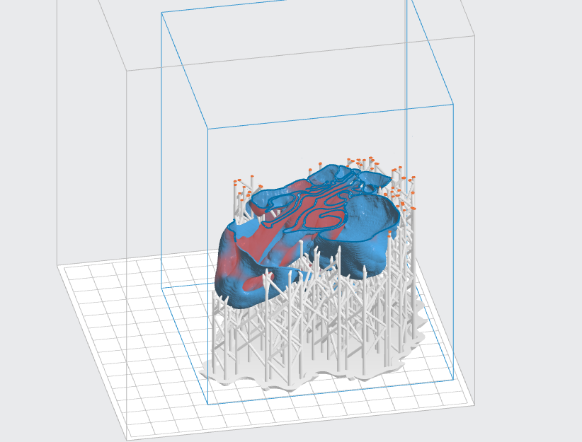
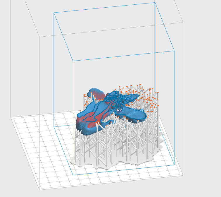
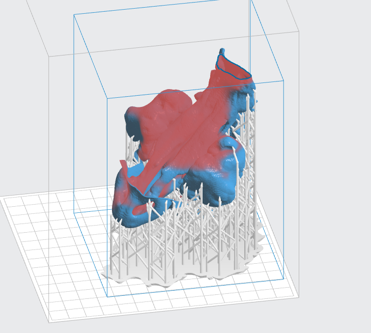
Side note. As you can see on the images there is a lot of red. That is so because I do not have any internal supports (cant have them for this project as I need to track something inside the print). If I add internal supports almost all the red disappears.
That’s different. Can you print them in 2 pieces, and then join them with resin after the print?
Showing a slice through it would be more helpful.


I probably could. But part of me doesn’t really want to deal with matching the parts and the other part of me wants to challenge the printer to see what is doable.
Wow, that looks like a pretty thin wall. I’d be worried about local minima inside the enclosed volume. I’m not surprised a thin surface like that is marked red. It may still print without internal supports, but only if there are no internal local minima or big spans, and even then, those are thin walls… But it could come out beautifully.
You are correct. They are pretty thin. After spending the last 6 hours going through the print layer by layer I think i eliminated any floaters from the print. Additionally what I did is create supports while having internal supports turned off. Then went back in and used the edit supports function while having the internal supports turned back on and strategically placed them in some spots internally where I knew they would not be in my way later on. Gonna run the print and see what happens.
However having now done this I think it would be good to have some things changed in that function:
- When putting in supports in an edit mode i was not able to see what layer i’m on while scrolling. It would be nice it you can see that since I was going back and forth between the edit and regular scrolling
- Since supports can change direction anyways it would be cool if you could create a custom pathway for the way support is going to run. Understanding that there do need to be certain limitations of how it can run so that it is actually doing its function of supporting
- while going through slices if I see the point that needs a support it would be great to be able to mark it right then and there so that by the time you go back to edit supports mode you know exactly which area you are triggering. I found it cumbersome to go back and forth since in slicing mode i saw a slice and a point but by the time i went to create a custom support i had to start from scratch and find that point again since I was looking at an entire model.
- additionally even though i completely understand why the slicing is in different directions between the slicing mode and edit supports mode it would be a benefit to be able to slice in the same direction (if you could switch between which way you are going) to make it easier in finding the spot in question
I only recently started working with Form so if someone is aware of how to do those edits described above I would appreciate any feedback.
Thanks all for your help.
Also I do understand that it probably would be best to print the model in 0.025 due to the wall thickness being so small however I am going to try and do it 0.1 both to challenge the printer as well as to have a faster print time.
I disagree, 25 um has to make ultra-thin features and have them hold up; 100 um is likely to print better.
Sounds good. Thank you. So far the print is going strong and no problems. Well one problem of me missing one floater so I paused and took it out to continue the print without blocking the laser. Likely it was not in an area that was of most importance so I corrected that on the print file and if I need to print another one it should have no problems.
Can’t wait to find out how it all worked out. I also agree that the walls seem very thin. But then again, I do jewelry. Just the number of supports makes me all twitchy!