Would it be possible to print a thin walled object with straight edges straight on the platform without supports? What would be the minimum recommendable thickness of the wall to do so?
The idea here is to print a very large model (a couple of feet long) in many small pieces. I would shell the model and only print the ‘surface’. I can make that surface any thickness I want.
Another consideration obviously is dimensional accuracy. Hundreds of thin walled parts would need to fit together like a jigsaw puzzle being assembled from the ground up. Remember that there would be no mass in the interior of the model since only the ‘surface’ would be printed (to save lots of time and money).
I’m also interested to know if even with supports the dimensional accuracy would hold up over hundreds of pieces.
Your ideas / suggestions are very welcome. Basically I need to find out whether this is possible to do to know whether I should buy the printer or not.
P.S. I am mostly looking to know whether I can do this on the new form 2. Older models I know for a fact it would be very difficult if not impossible.
My GUESS is that a flat piece like that with no support would just bust off.
But WHY not just engineer some internal structure, maybe even a puzzle locking system for all the parts?
Your going to use up resin and build time for the supports anyway…
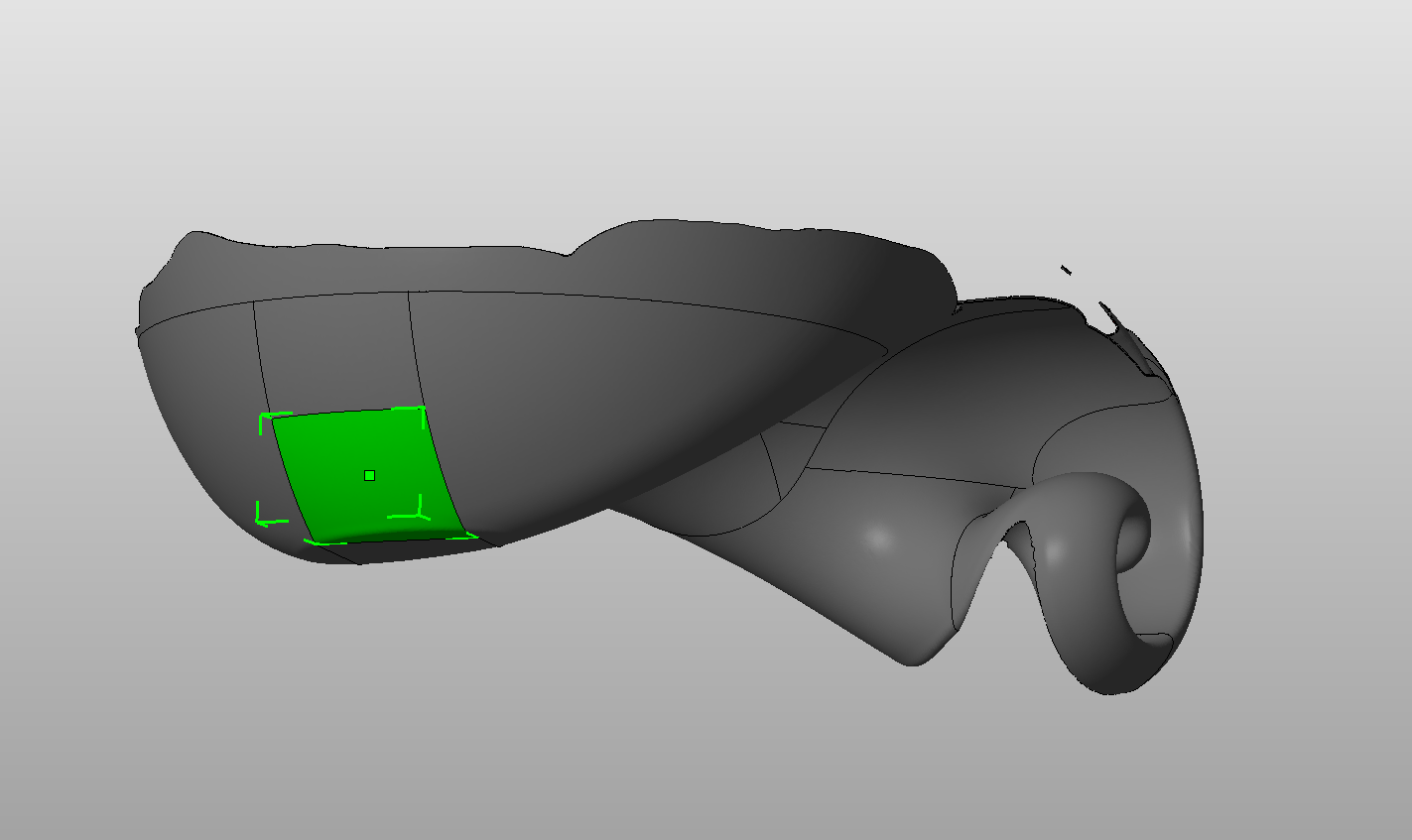
Hi Isaac. You have a really interesting question. My gut here says “yes you can do this”. I would try a shell thickness of 2.5 to 5mm. Orient it such that it is as close to vertical as possible and so that it feels the least torque from the slide (i.e. it faces the front of the printer). I would also create a raft in your CAD software that is fused to the part. After cleaning, you would saw off this raft and sand the part down to the correct shape. I’ve included a picture of what I have in mind. If you give this a try, let us know how it turns out.
You could try, but that would be a really impractical way of using this type of printer, I have a project currently where there’s a large part that’s about 12" long, have to split it up into about 6 big pieces and with the Form1+ the pieces didn’t really line up that well (though I was able to force them together). With the Form2 I’m sure it would do better, but for something like what you’re doing it would be a huge pain, not to mention very expensive. Since what you’re printing isn’t detailed, it would be much better to buy an FDM printer which could do larger objects like that more easily for a much lower cost.
Hi Isaac, I have worked on similar projects where I had to join a thin shell to another one because the print volume was smaller than the design. I would recommend (if it does not affect your design) to add some vertical ribs to the shell in order to maintain dimensional accuracy. Also, I have had success putting in matching sets of small holes where parts meet, so that I can easily alight them by gluing in small (0.0625") pins that span the two parts.
@Draconius Not exactly sure what you mean. To make an internal interlocking structure I would have the make the model solid.
@CraigBroady thanks for your input. I think a slightly thicker shell would also help. The problem with the raft if its fused it messes up the model dimensions and its gonna be significant clean-up work. Is there a way for the preform software generate only the raft and would this make sense?
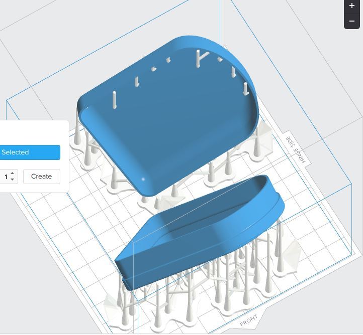
I tried changing some settings to get a raft and few supports (see attached pic) would something like this be more or less supported than the piece by itself?
I also read that the first few layers compress so if I put it by itself this would be a concern for the dimensions of the model.
Would like to know what you think about the dimensional accuracy in general holding up over hundreds of pieces.
@Zachary_Brackin I agree. I have two FDM’s and its what I have been using for all my projects. I will say that with deformation, supports, etc. the discrepancies can be huge between parts. And for more complex models its just not possible to do it on an FDM for those reasons. That’s where I was thinking the form might come in. I agree its not the ideal use case of the printer but the question is, can it do it? The alternative would be to print it in SLA in a bureau which would cost the same as getting a form2 (actually slightly more), so as expensive as the resin is, it doesnt come close to the alternative. So trying to choose the lesser of two evils here.
@bchan That’s a great idea, thanks for the tip. Do you have an easy/fast way to add those ribs that you use? The prospect of aligning ribs perfectly to hundreds of models is not a pleasant one.
Also can you please elaborate on the pins? I didint quite understand what you meant. Do you mean you punch holes in the model prior to printing and then you run like a wire through them to fasten them together? a photo would be worth 1k words in this case
@IsaacKatz , what you have there would definitely fail. The part would rotate about that sparse line of supports (like a hinge) during each peel cycle. I have created something similar to your idea using the support structures built. I recommend turning the point size to way higher then 0.60mm. You can see that instead of sparse support points in the middle of the part base, they are dense around the perimeter. This way, the part can better resist the torque it will experience during a peel.
Makes sense @CraigBroady thanks for the input. Did you make all those supports manually? Because I cant seem to find the settings that would give me a similar result automatically.
Also, is there a way for preform to just generate a raft for your model without supports?
In regards to the other topic, if I were to put it directly on the platform with a slightly thicker wall, would the first few layers that get compressed significantly affect the dimensional accuracy of the piece? Or would it be negligible (ie. I would consider .2mm negligible on a piece like this).
@IsaacKatz I made those supports automatically (slope multiplier reduced to minimum) and then edited the supports to add/remove as necessary. It would probably be just as quick to generate them all from “edit supports” mode.
No way to generate raft without supports.
Compression is generally less than a millimeter, but it may vary from tank to tank, platform to platform, and across the build area, as well. The first several millimeters are exposed a bit more during early layer routines, so they may look a bit different. Normally this region is just in rafts and support structures.
Here is a container I had to print for a customer that had 1mm wall thickness. The part came out great and the cleanup wasn’t too bad. I put the bulk of the supports where it was easiest to sand.
As shown, if you get the proper angle on the print there is no need for side supports. What I also found out is I need to use the finest layer setting of .025mm. I’ve just finished printing HO scale (1:87 scale) empty 55 gallon steel drums along with some with lids on them. All came out perfect. The side walls of those drums are about heavy paper thickness. For comparison the drums are 7/16" (11mm) high and 1/4" (7mm) diam. The walls on the empty drums are .025" (.14mm) thick. Again, I only use Grey and this is on a Form1+.