Form 1 / 1+ Aftermarket laser questions

Based on OpenFL’s config values it looks like the laser power in mW is controllable by the printer. It also seems the recommended max power is 62 mW.

I have two Form 1+'s with dead lasers (both started flaring) so I am in the process of trying to source a new laser for the machines that are cheap enough. So far finding 100 (ish) mW 405 nm lasers hasn’t been all that hard. I should even have control over the max current via a pot on the driver board of at least one of my selections. What I don’t really know is what the “max” current of the laser should be and how the Form 1/1+ tries to modulate the overall laser power. If I had to guess I would say it likely uses PWM to pulse the laser but I’m not sure.

My other question regarding the laser is how large the dot should be. I imaging both a larger dot and smaller one than expected would be a problem. Since the new laser is focus-able as opposed to the set optics of the lasers FL ships, I will have control over this.

Regarding what I have bought to attempt to swap in…

This is what I want to avoid, too expensive but it has some useful stats.

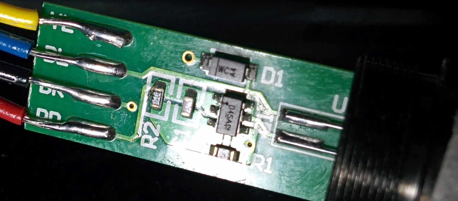
Early attempts at figuring this out led me to this:

Which has arrived and at least works in the sense that my Form 1+ can drive it. However I believe (just comparing it to my flaring laser) that it is wildly too weak (it is, <10mW) to be useful. This is an oversight on my part, don’t know how I missed that when I bought it.

Second attempt was this: https://www.aliexpress.com/item/32809148986.html?spm=a2g0s.9042311.0.0.600e4c4dOR3Flc correct wavelength, still too weak, might be too low voltage, probably not even going to try it.

Ok the real two lasers I want to try:


(that’s the first one), basically I boguth the Sony diode that matches what ppl here on the forum claimed was used by the Form 1+, and in order to make that work I ordered the holder and a driver I hope will work. This diode should be the correct wl, power, voltage, etc. but there’s still some unknowns, namely can I get the focus I need, can I dial in the max power correctly, etc.

I also found this (second real option): https://www.civillaser.com/index.php?main_page=product_info&products_id=727&gclid=Cj0KCQiAjfvwBRCkARIsAIqSWlNi-0lIXWDQCanOOsk4BTS1vOKLGfJGPRMDAGl_2vPHVDK-HFNQK4MaAm78EALw_wcB

Which is a pre-built module with the right wl and power. I don’t know if I can adjust the max current, but at least I know this will come with a driver that will work out and there’s minimal work to do on my part. Mostly just solder on the FL leads and shim the laser so it fits in the 15mm galvo clamp. That and figure out how to adjust the current.

I guess my questions are:

  • Am I crazy for attempting this?
  • How does the F1 control laser power dynamically?
  • What is the “max” current / power allowed through the F1+ laser?
  • Does anyone know how large the dot is suppose to be or how I would even really measure that other than trial and error? (140um??)
  • Anything I’m missing here?

Thanks,
-Cody

Enter “laser” in the search, you will find a lot of information about it.

I think you’re trying to re-engineer their laser control board, and that may be tough. A while back I was going to do a laser replacement on a Form 1+ I no longer have, and through a lot of research, what I found, and shared here was this:

The simplest way to fix this is to replace only the diode, and preserve the existing board and housing. The laser module in that old F1+ was easily disassembled by unscrewing the front lens. Since then Formlabs has seen to it that we can’t easily do this, but filling the tube with epoxy, which makes nearly impossible to take it apart.

I say nearly impossible, because some here have persevered in disassembling it.

Once it’s apart, you simply replace the diode on the same board, and hopefully you have a functioning laser. As for how Formlabs modulates it, we believe it’s through the built-in photo diode, which controls the output.

Here is the diode I purchased, but haven’t yet installed, as my current printer is still functioning fine.

So if I were you, that’s where I’d start.

P.S. It looks like you’ve only been here for a very short time. As Leolo mentioned above, there’s a ton of information on this forum if you would only search for it.

1 Like

I think I have another account but IDK, I’ve done tons of lurking and have been printing on FL printers for a few years now. I’ve owned 5x Form 1+'s, and only managed to totally destroy 3 of them at this point lol.

I tried to take apart the new laser on the Form 1+ and broke the ever living hell out of it. I couldn’t get the diode / lens module out without dremeling the black barrel part in half and that’s after carving out epoxy and dunking it in acetone spending hours and hours on that.

I expected to see what was posted here but in actuality what I found was a sealed lens / diode module with a board on the back of it (not pointed out, this was a round board). My laser is the two wire kind not the four wire one.

I’ll see if I still have the parts of it when I get home from work and post pictures.

Here they are.

Anyway after cutting the barrel in half the module with the lens and diode was still glued in place and still held on. I forced it and cracked the glass that surrounds the outside of that unit. Basically ripping the lens and diode in half. So RIP 1x laser.

I would say from my experience that there is no way in hell to replace the diode in the F1+ lasers.

Hence, I’m shopping for a new one.

As far as laser power goes, yes the ACP controller keeps the wavelength correct according to the temp of the diode or w/e. That’s not what I’m asking, I’m asking how the firmware runs the laser at 62 mW for some parts of the print and other currents at other times. You can see in OpenFL that the laser power is configurable for many parts of the print.

Again my guess is that the board they use lets X current in (regulated and I need to know X). And my guess is that the laser is pulsed via PWM to get less power. I suppose I can break out my logic analyzer and check, that’s probably the easiest way to get my answer on that.

Only other way I can guess is if they used a DAC and generate an analog voltage that the board does something with. Doubt it.

Assuming that gets answered, the next question is the dot size, which without a $2000+ laser profiler I doubt I’ll be able to measure so maybe I’ll just have to do some good old guesswork on that.

That and the max current the driver board delivers. I may be able to measure it or just reverse the whole driver board which is slightly out of my range of knowledge as I’m a software engineer pretending to know EE.

I also wonder why ppl have said that T018 and T038 diodes are the right ones. I’m guessing FL changed diodes between the F1 and F1+?

Is the Sony T038 the F1+ laser diode and the T018 the F1 laser diode?

Does anyone know why they switched from a 4 wire connector to a 2 wire? What did the other two lines do?


Not sure what the slit in that reflective thing at the end of the module is. Anyone know? It’s possible I damaged it in removal but I doubt it?!

1 Like

I’m thrilled to see someone else looking for a solution to replace the Form 1+ laser. Maybe we can help each other.

I can tell you for sure, do NOT buy that first Aliexpress link you posted:

I bought one and it did NOT work. First, it put out too much power, and actually burned right through my test sheet (I’m also skeptical it even has a photodiode for feedback). Then, it stopped working altogether. Returning it has proven near impossible, despite assurances from both AliExpress and the seller that it could be returned if it didn’t do the job.

Here’s a diagram and some measurements from my original laser that might be of help: Aftermarket Form 1+ Laser Replacement. The reply from @Marshall_Banana was very informative.

I wound up buying some of these, and am waiting for them to arrive from the UK (I know, it’s silly ordering from overseas, but another user said that exact one worked for him):

I believe the extra leads are for the photodiode, which is used for feedback - on my laser it looks like the light goes through a beamsplitter before leaving the module that sends a portion to a photodiode to monitor actual output (in realtime?).

I’m a little concerned by your comments about disassembling the module. I haven’t attempted to rip mine apart yet, and would be super grateful for advice from anyone who’s done it already.

What’s really weird, is the OP’s Form 1+ laser only has 2 wires. I thought all F1+ were 4 wire lasers.

BTW, I found another photo of the Form 1 Laser board, showing the closeup of the components.

The best thing you can use to de-pot epoxy filled units is methylene chloride. Some caution for other plastic parts you don’t want melted.

I know eh? That threw me through a loop, too. That’s a nice board photo btw, thanks.

Thanks for the tip. Unfortunately it’s not easy for me to source, and I’m a little wary of all the dire health warnings. Might sulfuric acid be a reasonable (if less effective) alternative?

Exactly the information I’ve been googling for. Thanks!

No. MC is the only really good de-potting chemical.

Heat will soften up epoxy and make easier to remove from the encased components. I once had to do this on a Toyota Supra ECU, and found that boiling it for about 10 minutes it had softened the stuff up just enough to be able to take it out of the casing, then using a flat blade screw driver I was able to remove chunks of the stuff until I exposed the board. Having a heat gun or a hot hair drier handy also helps in keeping the epoxy soft while your working on it.

Wow we’ve got some great replies here. Sorry for being AFK a bit. Yes I have two F1+'s with two-wire lasers, both lasers are flaring, both are surely FL lasers. I have reason to believe that at least one of the machines is the latest F1+ model. If I had to guess, I’d say FL moved some of the work to the new laser board and that this module might be a sort-of between design (between the F1 and F2?) I don’t really know.

The machines I have are one F1 that I bought on eBay a while ago and one my company gave me after having it serviced many times and eventually giving up on it. When I got the company machine home, I tried everything to get it to work but it’s laser was the problem and so only by swapping lasers with my good machine was I able to use it.

It’s the darker silver casing variety which I believe is the newer look.

Fantastic thread. I just can’t figure out why my laser looks different from everyone else. Am I seriously the only one here with a two-wire laser module?

Alright I had some time today so I busted apart the diode assembly. Here’s the pictures:

It’s entirely possible I lost a SMD component or two when removing the epoxy. R2 has clearly let go and C1 looks MIA, but R1 I can’t be sure of. Solder pads don’t look broken to me. Anyway this board looks stupid simple to me.

How do I figure out the diode model # / manufacture?

1 Like

Scratch that, I found the other two SMD components in the epoxy lol.

Can anybody else reading this topic check their lasers insider their F1+ printers and verify the number of wires coming out of their laser module?

I have personally seen the inside of 4 of these printers, two of my own, and 2 that I helped friends with. All had a 4 wire harness.

What about everybody else? Did FormLabs make changes to the F1/F1+ that resulted in a 2 wire laser?

@cody1

Did you buy this printer new from Formlabs, or was this a 3rd party purchase? Is it possible the printer had been altered?

4 here

Unexpected development:

Sent this guy a low offer I wasn’t expecting to land. Huh, guess my 2x F1+'s are either toy machines or getting parted.

Last time I parted an F1+ I got more in parts than selling the machine whole so that’s what I’ll probably do.

Well, I guess we’ll never know the answer to my question, but Good luck with the Form 2 all the same.

To be honest, once my F1+ bites the dust, I probably won’t buy another Formlabs printer unless I came upon a really crazy deal. For the last 5-6 months I’ve only used my Photon, and haven’t even turned the F1 on.