Hello I didnt get my Form 2 yet but was wondering if its possible to create multiples of a small pieces connected kinda like sprues? Would I be able t do something like this?
Heres a sheet of them to shoe an exmple of the size of the clips:
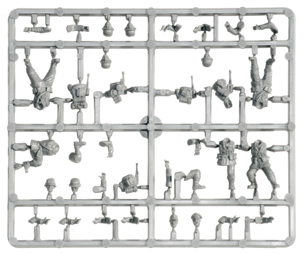
wisdomknight, the photo that you show here is an injection molded set of figurine parts. The actual sprue is at the center of the array. The trapezoidal shaped thing that you are calling the sprues actually is the runner system. The runner system is a series of channels for the molten plastic to travel through in order to reach each part cavity in the mold. The truncated areas of the runner that attach the runner to the actual parts are called gates. So this is the convention used for injection molding these figurine parts. But for 3D printing, why would you want to use the runner system configuration? Why not have a support for each of the pieces in the above photo? Maybe I am missing an assumption or requirement that you might have here. But for me, I think you need to think about making the parts from a 3d printing perspective, not with a perspective of making injection molded parts look 3d printed. As far as I can see, there is no reason to 3D print the runner system. But again, maybe I am missing something that you are wanting or need to factor for.
Maybe this will make it more clear.
I was wondering if I can not only do this but have layer of clips going in the z axis also so as to have a 3d dimensional array of clips
wisdomknight, I think it is getting clearer to me now. So you want to print the “H” shaped parts that are in your whiteboard sketch above - not the injection molded soldier figurines - is that right? If that is the case, then you can use PreForm to take your one 3D model of this “H” shaped part and duplicate it as many times as it will fit within the real estate of your build platform. And then the supports for each part should be connected to each other so that technically, the parts are not connected by the red colored features, but instead the supports will be connected while the “H” shaped parts remain separated from each other. As far as building up multiple layers of parts in the Z direction…I just don’t know about that one. There might be a trick to do this that I am not aware of.
Yes thats exactly what I am trying to accomplish.
Could I control the supports so they are in place and connect at the ends of my parts?
And WILL these print with supports configured like THE RED SPRUES?
wisdomknight, I believe the answer is yes - - I am not sure if I am correctly understanding your first question. Here is a shot of my creating an array of the same part from the PreForm. You can see that each part is separate, but the supports are connected together:
I think I understand the second part of your question. I believe you are asking if you can stack parts like you can in a powder bed printer. The answer is sort of. You would have to have 1 file with the parts where you want them (already stacked in all 3 dimensions). Then using the internal supports you could make sure your parts are properly supported. In reality, you do not want to do this. It won’t save that much time overall as you just have to build your tray out like Ken’s picture, when the print finishes just rinse and repeat.
I am gathering the reason you want to do this is to set a print up over a weekend or overnight and get back to work with a printer full of parts. The real problem with this (that I see) is if you have a failure early on, I think you will end up with a huge waste of resin only being able to (hopefully) salvage some of your parts.
Thanks David for your input as well.
Maybe I just have to get the Form 2 first and experiment with it and Preform before attempting something like this.
I just need dozens of these clips and I just cant afford to get them injection molded yet until my project is up and running and succesful.
wisdomknight, I think you may be able to print a fair amount of your flat plate-like part by angling the part (like I have done in my example that I shared above) and then making an array of them. Once you make the array, then one part may “overhang” an adjacent part so that the “part density” on your build platform will be much more than if you print the parts flat. By the way, you will not want to print the parts flat anyway, because the bottom surface of your plate will end up being wavy and quite uneven (due to there being no support of the liquid resin as the initial large surface area layer gets initially cured by the UV laser).
As some have suggested, stack your parts in a 3d array with spacing. add small connectors with smaller contact points to connect them all together. (you could actually do this by adding them to one parts and then duplicating in a 3D grid. That is shown in the pics called Array 1 and Array 3. I did it quickly so did not make pointed connectors. As you can see Preform added its support material so my manual supports probably did not help.
In the second example, I just to the part into NetFabb Pro, duplicated in an array with defined spacing, exported the entire array as a single STL. Loaded into form and let it do its thing. *Array 3, Array 4). you can see from the red highlights there are some support issues, so spacing may be a problem
You can get much much better results by doing the supports yourself, the software can make errors where it puts points where they aren’t needed, or it puts points inside the object if you have separate objects intersecting that don’t need extra support since they intersect. It also doesn’t take into account how close to put supports, so you can spread them out more so that you get better results and less supports. Most prints I see people do have more supports than are necessary. The red coloring is also not always accurate
Thanks Zachary, I havent used PreForm yet.
Im guessing I can control supports in the software? Or do I have to model then in before I bring them in Preform?
Yes, the support system in the software is probably the best I’ve seen, but the results using the automatic generation isn’t as good as placing the points yourself. What I do is have it generate automatic supports and then go into edit mode which shows small spheres on the object where each support touches the print and then I remove the points I don’t want and add new ones. What’s good about their support system is that it creates branching structures between supports and angles them around stuff so you get a great support structure that doesn’t use a lot of resin-at least comparatively.
Another option you might try is to export the array of parts as a single STL. You can then import it into Meshmixer (free) and have MM orient it. MM can generate very good tree branch style supports. This can be exported as an STL and the imported to preform and printed without having preform orient or generate supports. WARNING I have only done this with an FDM type printer, not a Form, so try it with something small and watch at least the start of the build.
Has anyone printed on a form just using MeshMixer generated supports?