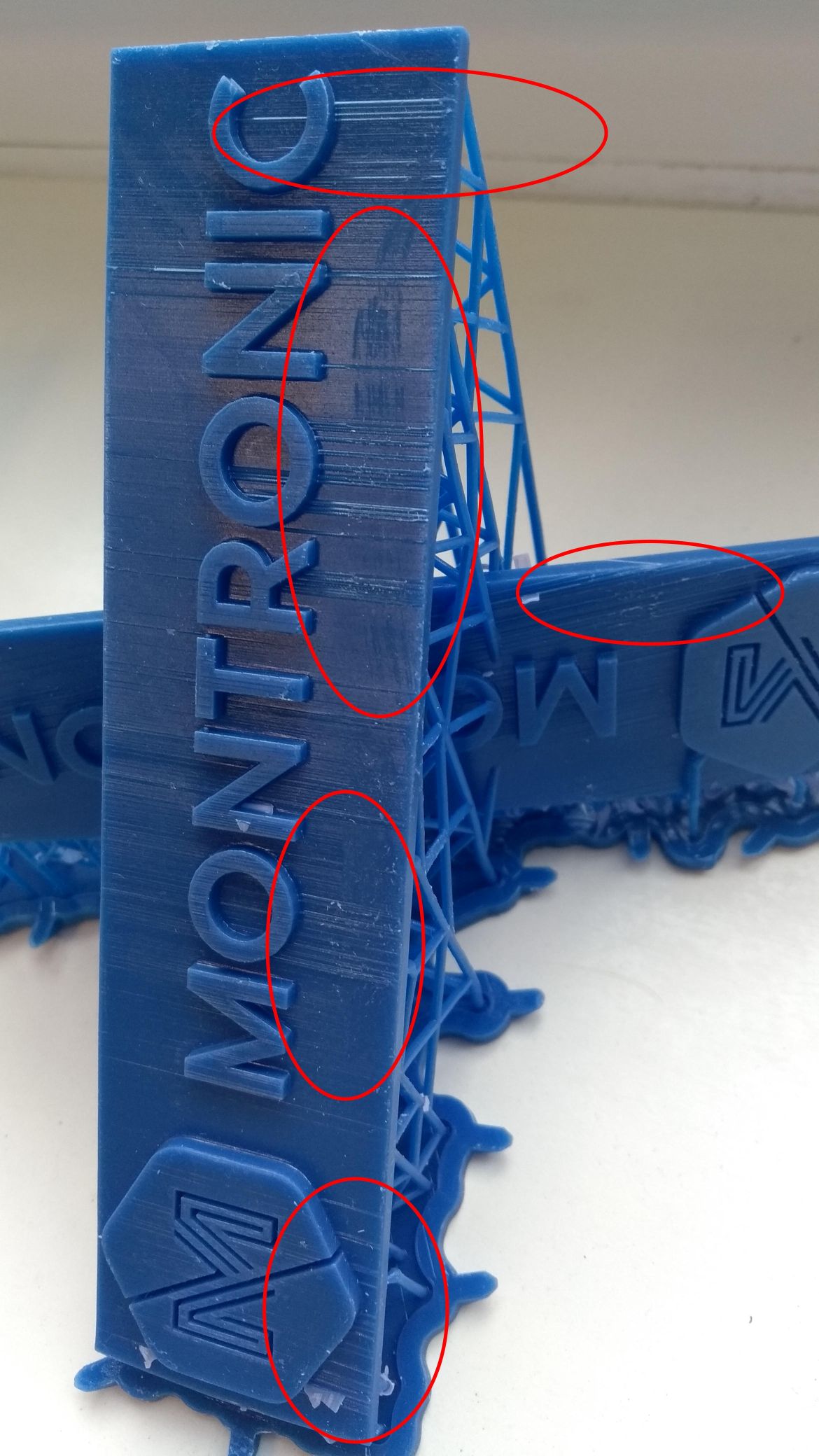
Ich habe immer wieder Probleme das glatte Schichten nicht glatt sind, sondern “Ablagerungen” aufweisen. Diese Ablagerungen sind parallel zur Z-Ausrichtung.
Es tritt bei verschiedenen Materialen (Flex, Though, Castable, Clear - andere habe ich noch nicht verarbeitet) auf. Für jedes Material habe ich einen eigenen Tank. Die Materialien, Tanks, und der Drucker selbst sind ca. 2 Monate alt. Das Problem trat von Anfang an auf. Der Drucker steht in waage, schattig und in einem Raum mit normalen klimatischen Zimmerbedingungen.
Es ist nicht bei allen Objekten, aber oft. Wo es aufgetreten ist es reproduzierbar. Ich habe keine Ahnung wieso und würde mich mal über Hilfestellungen bzw. Hilfestellung zur systematischen Fehlersuche dazu freuen. Anbei einige Bilder.
aktuell habe ich gerade Castable auf der Maschine und habe versucht das Fehlerbild durch unterschiedliche Ausrichtungen der Bauteile näher zu erleuchten:
I’m going to answer in English because my Deutsche is so horribly rusty.
Those lines look like the issue discussed in this thread. What was happening in that case is that the model was composed of separate shells which just barely touched. In this case, is the back of the extruded letters coplanar with the front of the base? If so, it is probably this issue.
What is happening in this case is that when PreForm slices through the plane that’s shared by the two objects, the math gets rather degenerate and there’s a lot of confusion about what portion of that slice is inside and what portion is outside. There are two ways to make this more robust.
If your modeling program supports it, you can do a “boolean union” to combine the separate shells into a single one. This is the preferred approach.
If not, then you can push the back of the letters a tiny ways into the base. Something on the order of the layer size you’re going to print at will be more than sufficient. The math of two shells which intersect is much simpler than the math of two shells which just barely touch.
Mit welchem Datenformat arbeitest Du (OBJ oder STL)? Wenn STL, mit welchem Programm bereitest Du den Druck vor (Fehlerkorrektur)? Kann dieses Programm eine einzige Shell erzeugen?
Ok, i understand that the lines are just a math “Problem” from my stl to Preform? It is out of question that is anything about the Printer Hardware, rigth?
An the orientation ob the object is also not the Problem, just in the litle way that preform calculate something and the lines arise.
One Thing i didn’t understand, when prefom slice the object withe the lines, why can’t i see them in Preform Window?
All objects are drawed by sketchup (pleas don’t laugh) and exportet as stl. i put the stl file directly to preform. I try to find some time to do the Change that i put the objects a Little in the base back.
Should a put my stl first in aney other tool to do some errorhandling? what do you mean with singel Shell? what program do i need?
Thanks a lot for suggestions, i will test soon as possible.
bye,
Mario
Nearly every CAD program produces more or less errors when exporting to STL.
You can use the netfabb online services (via Microsoft Live) to check and repair.
And it’s a good idea too, to union all parts before exporting.
@majo schau mal bitte nach, ob dein Glas penibel sauber ist. Ich hatte ähnliche Muster vor einer Weile aufgrund eines verschmutzten Spiegels/Glases. Es reicht schon ein leichter Schleier, welcher diese Schichtbildung hervorruft.
Ich kenne das Problem im Zusammenhang mit SolidWorks,
Der Fehler tritt immer dann auf, wenn Teile mit mehreren Körpern/Features in SolidWorks nicht vollständig miteinander verschmolzen worden sind.
Schau doch mal in SketchUp, ob dort ähnliche Optionen (Verschmelzen, verbinden, usw.) verfügbar sind.
Thaks for big relpy. I’m sure that is nothing about static dirty optics because when i get object with lines - the lines are not dependen on any special object directionoder placement - when i placed same object on other Position the lines were there again.
While we writing i’ve put in sketchup the base structure of the rectangel about 0,5mm higher in the leters like mgarrityhat told in 2.
Here is the Result, it seems to be a fixup. Reals thanks a lot for this! I dont know anythything about some Options to do this automaticly, but i will try it on other times, like il will test the result of netfabb with the first file.
Looks great! I’m glad that helped. And yes, if you’re using Sketchup, then this approach of overlapping the shells is probably your best choice. Doing a boolean union in Sketchup can be a challenge.